
Exhaust gas treatment technology

A treatment process and exhaust gas technology, applied in the direction of combined devices, dispersed particle separation, chemical instruments and methods, etc., can solve the problems of non-standard emission of exhaust gas, incomplete purification of exhaust gas, etc., to avoid substandard emissions, reduce pollution, and convenient operation Effect

Inactive Publication Date: 2019-05-21
中科天龙(厦门)环保股份有限公司
View PDF4 Cites 1 Cited by
  • Summary
  • Abstract
  • Description
  • Claims
  • Application Information

AI Technical Summary

Problems solved by technology

[0003] In view of this, the present invention proposes a waste gas treatment system, aiming to solve the problem that the existing waste gas purification is not complete and the waste gas cannot be discharged up to standard

Method used


Image

  • Exhaust gas treatment technology

Examples


Embodiment Construction

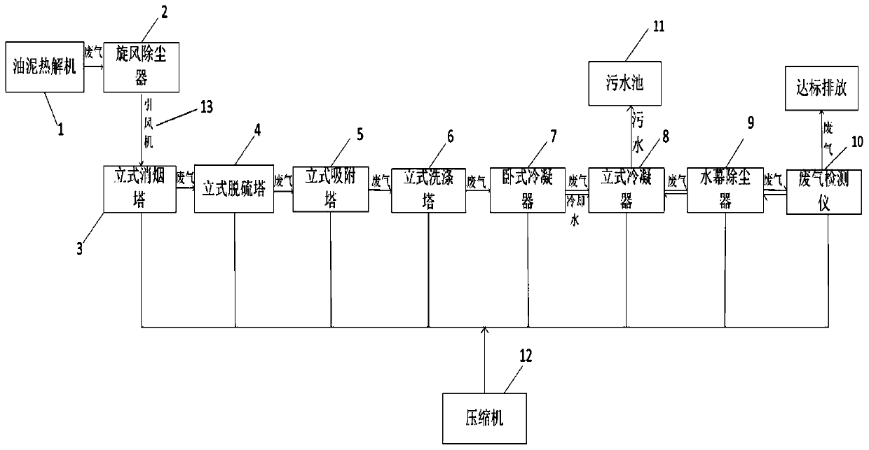
[0023] Exemplary embodiments of the present disclosure will be described in more detail below with reference to the accompanying drawings. Although exemplary embodiments of the present disclosure are shown in the drawings, it should be understood that the present disclosure may be embodied in various forms and should not be limited by the embodiments set forth herein. Rather, these embodiments are provided for more thorough understanding of the present disclosure and to fully convey the scope of the present disclosure to those skilled in the art. It should be noted that, in the case of no conflict, the embodiments of the present invention and the features in the embodiments can be combined with each other. The present invention will be described in detail below with reference to the accompanying drawings and examples.

[0024] refer to figure 1 Shown is the process flow chart of the embodiment of the present invention, which includes: sludge pyrolysis machine 1, cyclone dust...


PUM


Abstract

The invention provides an exhaust gas treatment technology. The technology comprises the steps of waste gas dust removal, wherein waste gas is introduced into a cyclone dust collector, and waste gas is introduced into a smoke abatement tower and subjected to participate precipitation by the smoke abatement tower; waste gas desulfurization, wherein waste gas obtained after dust removal is introduced into a desulfurization tower and subjected to desulfurization treatment by the desulfurization tower; waste gas purification, wherein waste gas obtained after desulfurization is introduced into an adsorption tower, harmful gas is absorbed away by the adsorption tower, and the waste gas is introduced into a washing tower to be further purified; waste gas condensation, wherein waste gas obtained after purification is introduced into a horizontal condenser and a vertical condenser in success for condensation and liquidation; secondary waste gas dust removal, wherein waste gas obtained after condensation is introduced into a water curtain dust collector for secondary dust removal; waste gas detection, wherein waste gas obtained after secondary dust removal is introduced into a waste gas detector for detection, waste gas is detected to reach the standard and exhausted, otherwise, waste gas is introduced into the water curtain dust collector for dust removal again, and the steps are repeatedly executed till waste gas reaches the standard to be exhausted.

Description

technical field [0001] The invention relates to the technical field of waste gas treatment, in particular to a waste gas treatment process. Background technique [0002] At present, with the sustained and rapid growth of the national economy, the demand for oil resources is increasing. With the increasing amount of sludge, there are more and more sludge treatment processes. During the sludge treatment process, a large amount of waste gas will be generated. If it is discharged without proper treatment, a large amount of toxic gas will be discharged into the air. , making the air quality worse and worse. At present, the treatment of industrial waste gas mainly adopts activated carbon adsorption method, catalytic combustion method and other methods. However, the purification effect of these treatment methods is not very good. The exhaust gas discharged into the air contains dust and toxic gases, and the cost is high. Contents of the invention [0003] In view of this, the p...

Claims


Application Information

Patent Timeline
Patent Type & Authority Applications(China)
IPC IPC(8): B01D53/00B01D53/02B01D53/14B01D53/18B01D50/00
Inventor 傅太平戴东雄高志峰吴文强傅汉文
Owner 中科天龙(厦门)环保股份有限公司
Learn More