
Sludge treatment process and system

A technology for sludge treatment and treatment process, which is used in sludge treatment, water/sludge/sewage treatment, dehydration/drying/concentrated sludge treatment, etc. problems, to achieve the effect of reduction and resource processing, low operating costs, and small footprint

Active Publication Date: 2015-01-07
山东博润环保科技有限公司
View PDF3 Cites 7 Cited by
  • Summary
  • Abstract
  • Description
  • Claims
  • Application Information

AI Technical Summary

Problems solved by technology

[0004] However, the above-mentioned treatment process has the following technical defects: 1) The heat transfer evaporation drying process consumes a lot of heat and energy consumption, and the sludge will emit a large amount of malodorous gas during the heating process; 2) The conventional mechanical dehydration and drying process requires Add a large amount of additives, the cost is high, the effect of dehydration and drying is not obvious, and the sludge may be converted into chemical sludge during the treatment process, which limits the subsequent disposal; 3) The anaerobic fermentation treatment process is affected by the change of sludge composition 4) The energy consumption of aerobic fermentation treatment is high, the basic investment is large, and it is greatly affected by the change of sludge composition; 5) Toxic and harmful gases such as dioxin may be produced during the process of co-incineration treatment, and It cannot completely solve the pollution problem of toxic and harmful substances such as heavy metals contained in sludge; 6) Simple landfilling has been gradually banned in recent years, and this treatment method will cause serious environmental pollution problems; 7) Fertilizers produced from sludge , may contain pollutants such as heavy metals, which limits its use and is only suitable for landscaping, and there is a risk of causing environmental pollution and food chain pollution

Method used


Image

  • Sludge treatment process and system

Examples


Embodiment Construction

[0023] The specific embodiments of the present invention will be further described below in conjunction with the accompanying drawings.

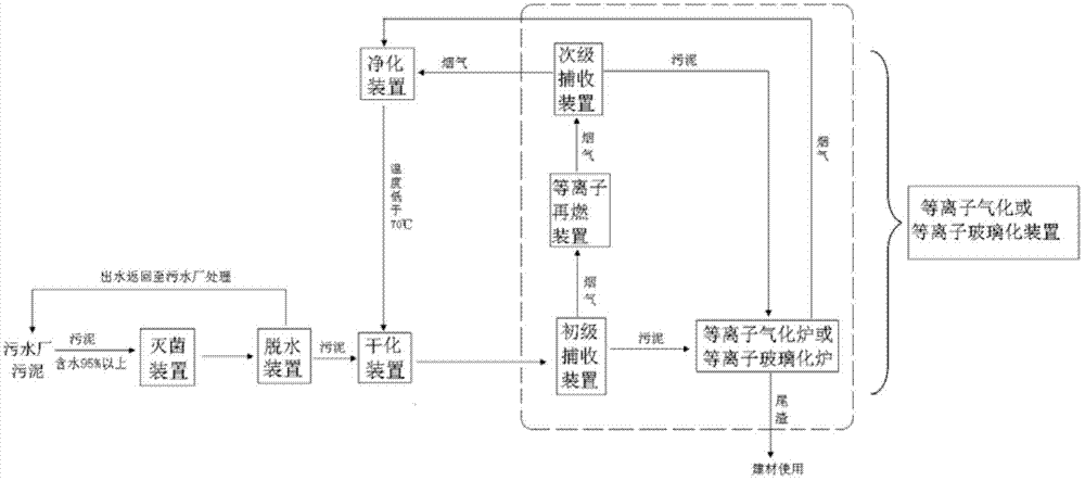
[0024] as attached figure 1 As shown, the sludge treatment system of the present invention includes a sterilizing device, a dehydrating device, a drying device, a plasma gasification or plasma vitrification device, and a purification device connected in sequence. The plasma gasification or plasma glass The sterilization device includes a primary collection device, a plasma reburning device, a secondary collection device, and a plasma gasification furnace or a plasma vitrification furnace, wherein the sterilization device can use an ultrasonic generator with a frequency not less than 40 kHz, and its water inlet is connected to the The sludge produced by the sewage treatment plant with a water content of more than 95% is connected, and its effluent enters the dehydration device; the dehydration device can use a mechanical dehydration device su...


PUM


Abstract

The invention discloses a sludge treatment process which comprises the following steps: (1) sterilizing sludge so as to kill microorganisms in the sludge; (2) dewatering and drying the sterilized sludge so as to reduce the water content of the sludge; (3) separating the dried sludge, carrying out high temperature plasma treatment on the separated sludge, and burning separated smoke; (4) carrying out sludge-smoke separation on smoke generated by reburning treatment, carrying out high temperature plasma treatment on the separated sludge again, and purifying and cooling the separated smoke. The invention further discloses a sludge treatment system capable of carrying out the sludge treatment process. The sludge treatment system comprises a sterilizing device, a dewatering device, a drying device, a plasma gasifying or plasma vitrifying device and a purifying device. The sludge treatment system can realize harmless, reducing and resourceful treatment for the sludge and does not generate secondary pollution, is safe and reliable, and can realize thorough treatment for the sludge.

Description

technical field [0001] The present invention relates to a sludge treatment system, in particular to a sludge treatment process using high-temperature plasma gasification technology for harmless treatment of sludge. The treatment system is suitable for the treatment of muddy solid waste such as municipal sludge and industrial sludge, and belongs to the field of environmental protection. Background technique [0002] Sludge is a product in the sewage treatment process, which has complex components, colloidal shape, unstable properties, perishable odor, high content of heavy metals, toxic and harmful pollutants, high moisture content, poor dehydration, not easy to dehydrate, and contains a large number of pathogenic bacteria and characteristics of parasite eggs. If this kind of sludge is not properly treated, it will cause great harm to the environment, human and animal health. [0003] At present, the sludge treatment process mainly includes two categories: sludge drying tre...

Claims


Application Information

Patent Timeline
IPC IPC(8): C02F11/00C02F11/12C02F11/10
CPCC02F11/00C02F11/10C02F11/12
Inventor 陈兵刘淑良谢新兵史桂平
Owner 山东博润环保科技有限公司
Learn More