Cooling, moisturizing and grouting integrated device and method for mass concrete

A large-volume concrete and concrete technology, applied in construction, infrastructure engineering, etc., can solve the problems of no good solution for concrete cracks, unavoidable internal cracks, and impossibility of concrete moisturizing and maintenance, so as to avoid temperature rise cracks and low cost , to achieve the effect of crack resistance

Active Publication Date: 2019-05-21
CHANGJIANG RIVER SCI RES INST CHANGJIANG WATER RESOURCES COMMISSION
View PDF8 Cites 6 Cited by
  • Summary
  • Abstract
  • Description
  • Claims
  • Application Information

AI Technical Summary

Problems solved by technology

A moisturizing mechanism is set up, but since there are no ventilation holes inside the pipeline, the moisturizing mechanism cannot moisturize and maintain the interior of the concrete
[0007] In the prior art, the curing devices for large-volume concrete cannot perform moisturizing maintenance on the inside of the concrete, and the internal cracks after the concrete is cured are unavoidable, but there is no good solution for the cracks generated inside the concrete in the prior art

Method used


Image

  • Cooling, moisturizing and grouting integrated device and method for mass concrete
  • Cooling, moisturizing and grouting integrated device and method for mass concrete
  • Cooling, moisturizing and grouting integrated device and method for mass concrete

Examples


Embodiment 1

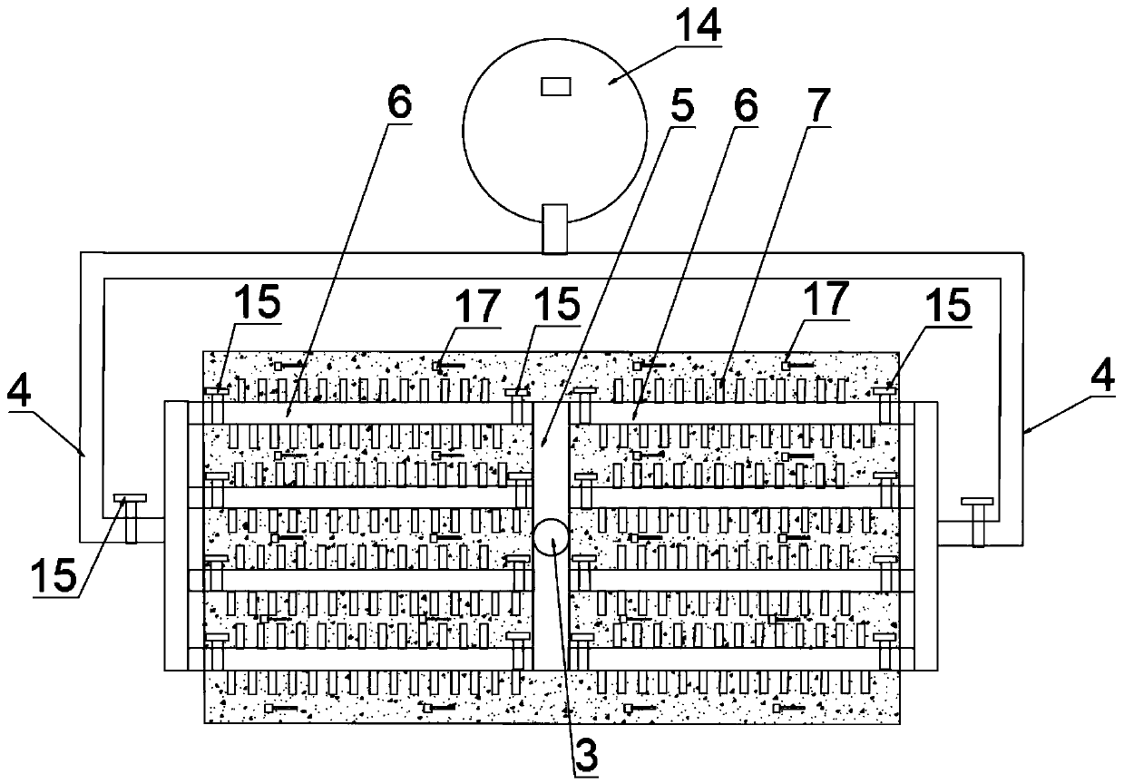
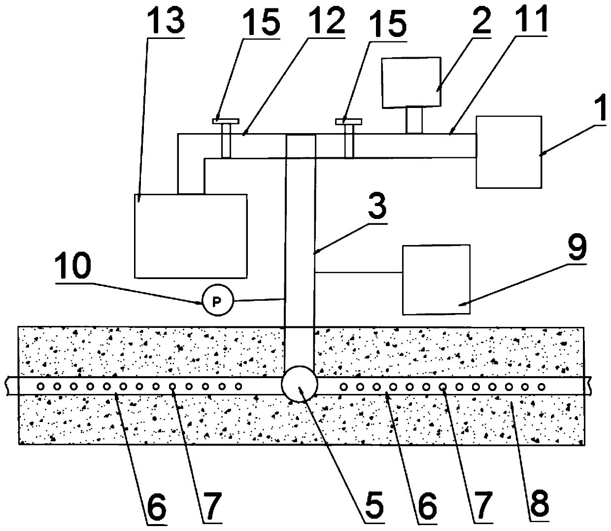
[0044] Such as Figure 1-3 As shown, the integrated device for cooling, moisturizing and grouting of large-volume concrete of this embodiment includes an air refrigerator 1, an atomizer 2 and an air-conditioning pipe; the air-conditioning pipe includes an air inlet pipe 3, an air outlet pipe 4, and a pre-buried concrete The air-conditioning buried pipe includes the air-conditioning main pipe 5, the air-conditioning branch pipe 6, and the air-conditioning branch pipe 7. The air-conditioning main pipe 5 is arranged horizontally in the middle of the concrete 8 and the middle of the air-conditioning main pipe 5 is connected with one end of the air intake pipe 3 on the surface of the vertical concrete 8; The air pipe 3 is provided with a pressurizing pump 9 and a pressure gauge 10, and the other end of the air inlet pipe 3 is connected to the low-temperature atomization channel 11 and the ultra-fine cement slurry grouting channel 12 respectively through a three-way pipe. The low-tempe...

Embodiment 2

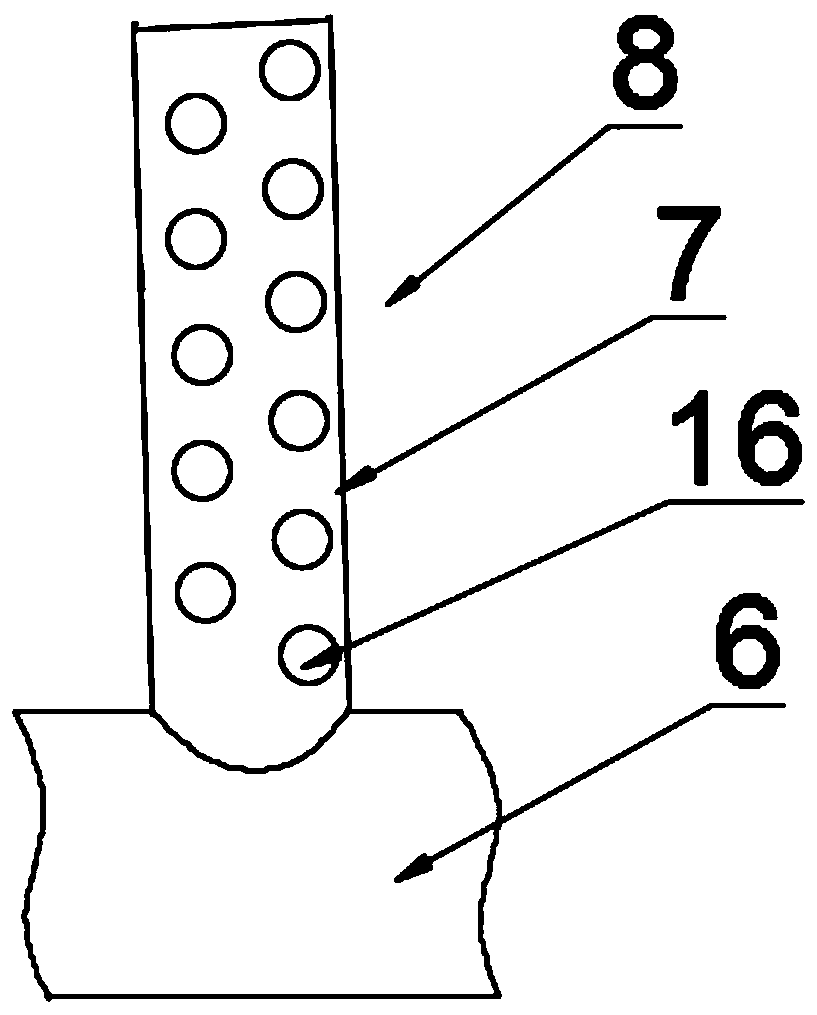
[0049] Such as Figure 4-7 As shown, compared to Embodiment 1, the cold air branch pipe 7 of this embodiment is provided with a one-way valve 18 for controlling the atomized water droplets or ultrafine cement slurry in the cold air branch pipe to flow into the concrete 8 unidirectionally from the air vent 16. The one-way valve includes a vent 1801, an elastic baffle 1802 and a stop 1803. The elastic baffle 1802 is arranged behind the vent 1801, and the stop 1803 is located on the side behind the elastic baffle 1802. The elastic baffle can be made of an elastic rubber sheet, more preferably an elastic material that is breathable and impermeable. When the pressure pump is working, the pressure of the cold air branch pipe is greater than the air pressure in the pores, and the elastic baffle is deformed and bent to the side and back, so that the air vent opens, and atomized water droplets or ultra-fine cement slurry enter the concrete from the cold air branch pipe. When vacuuming ...


PUM


Abstract

The invention relates to a cooling, moisturizing and grouting integrated device and method for mass concrete. The device comprises an air refrigerator, an atomizer and a cold air pipeline. The cold air pipeline comprises an air inlet pipe, an air outlet pipe and a cold air buried pipe pre-buried in concrete. The cold air buried pipe comprises a cold air main pipe, cold air branch pipes and cold air branch pipes. A pressurizing device and a pressure gauge are arranged on the air inlet pipe, and the air inlet pipe is connected with the low-temperature atomization channel and the superfine cementpaste grouting channel through a three-way pipe; the air outlet pipe is connected with the recovery tank; the two sides of the pipeline of each cold air branch pipe are connected with a plurality ofcold air branch pipes, and a plurality of vent holes are formed in the cold air branch pipes. According to the integrated device, the interior of concrete can be subjected to cooling and moisturizingmaintenance at the same time, the internal stress is greatly reduced, temperature shrinkage and drying shrinkage are reduced, and cracks are reduced; and grouting treatment can be performed to repaircracks in concrete.

Description

Technical field [0001] The invention belongs to the field of construction, and in particular relates to an integrated device and method for cooling and moisturizing grouting of large-volume concrete. Background technique [0002] Today, cracks are still a stubborn disease that plagues large-volume concrete structures. Research and practice have shown that temperature stress is the main cause of cracking in mass concrete during construction and even operation. During the construction period, a large amount of heat generated by the hydration reaction of the cementitious material in the concrete will cause the temperature of the structure to rise, and the temperature stress caused by the internal and external temperature difference caused by the temperature rise will easily cause the surface of the structure to crack. In the later period, the temperature stress generated by the overall cooling temperature difference under the action of external restraint is likely to cause structur...

Claims


Application Information

Patent Timeline
Patent Type & Authority Applications(China)
IPC IPC(8): E02D15/02E02D15/04
Inventor 李家正李明霞颉志强
Owner CHANGJIANG RIVER SCI RES INST CHANGJIANG WATER RESOURCES COMMISSION
Why Eureka
Try Eureka