Method for compensating inertial installation error of cabin assembly

A technology of installation error and compensation method, which is applied in the inertial field, can solve the problems of poor accuracy of navigation system and control system, installation accuracy that cannot meet the requirements, and difficulty in ensuring installation accuracy, etc., achieves small code changes, reduces processing difficulty, The effect of improving accuracy

Pending Publication Date: 2019-05-21
XIAN MICROELECTRONICS TECH INST
View PDF7 Cites 2 Cited by
  • Summary
  • Abstract
  • Description
  • Claims
  • Application Information

AI Technical Summary

Problems solved by technology

[0003] In the past, the assembly of cabin-level products used datum planes or positioning pins to ensure the installation accuracy between the inertial group and the cabin. However, this method is difficult to process, high in cost, and poor in operability in assembly. The cabin sections need to be installed in multiple stages, and each stage of installation will bring errors of different sizes and directions. Therefore, the installation error caused by multi-stage installation will be larger, and it is more difficult to ensure the installation accuracy
If the inertial group installation accuracy does not meet the requirements, it will directly lead to the deterioration of the accuracy of the navigation system and control system, and even directly lead to the failure of the mission, resulting in an irreversible situation

Method used


Image

  • Method for compensating inertial installation error of cabin assembly
  • Method for compensating inertial installation error of cabin assembly
  • Method for compensating inertial installation error of cabin assembly

Examples


Embodiment Construction

[0040] The present invention will be further described in detail below in conjunction with specific embodiments, which are explanations of the present invention rather than limitations.

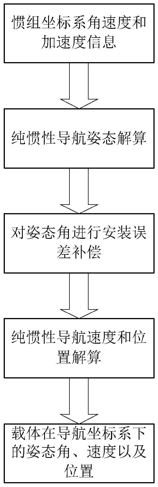
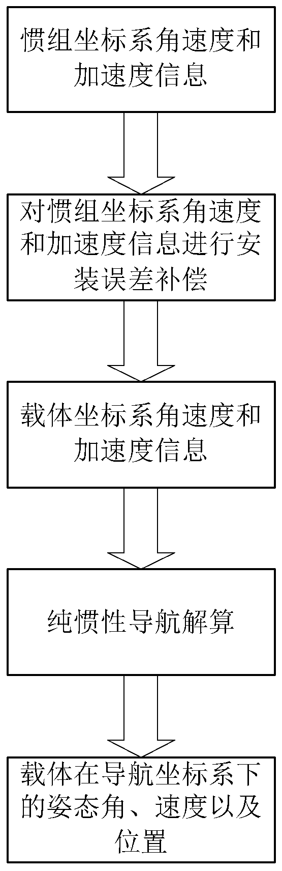
[0041] Due to the large weight and volume of cabin-level products, it is impossible to perform calibration compensation on the turntable, and the multi-stage installation between the inertial group and the cabin will bring installation errors of different sizes and directions. In order to reduce the The installation error between the inertial group and the inertial group improves the accuracy of the control system. The present invention proposes a compensation method for the inertial group installation error based on cabin assembly. This method is a software compensation method and does not rely on redundant hardware equipment and structural parts. It can effectively reduce the impact of installation errors on the control system; at the same time, this method does not need to consider the erro...


PUM


Abstract

The invention provides a method for compensating the inertial installation error of a cabin assembly. A rotation matrix C<imu>b from a carrier coordinate system to an inertial coordinate system is defined; pure inertial navigation solution is carried out by using angular velocity and acceleration information in the inertial coordinate system to obtain an attitude matrix C<n>imu and installation error compensation is carried out on the attitude matrix C<n>imu by the rotation matrix C<imu>b and an outputted attitude matrix is C<n>b, an attitude angle of the carrier under the navigation coordinate system is calculated based on the C<n>b and then a speed and position of the carrier in the navigation coordinate system are calculated; or data outputted by the inertia group are compensated directly by the rotation matrix C<imu>b, pure inertial navigation solution is carried out by using the compensated inertial group data, an attitude angle of the carrier in the navigation coordinate system is calculated, and then the speed and position of the carrier in the navigation coordinate system are calculated. Therefore, the accuracy of the navigation system is improved; the influence of the inertial installation error on the flight control system is reduced; and a solution to the inertia installation error compensation of the cabin product with the large volume and weight is provided.

Description

technical field [0001] The invention belongs to the technical field of inertia, and in particular relates to an inertial group installation error compensation method for cabin assembly. Background technique [0002] With the improvement of systematization, integration, and miniaturization requirements of weapon systems, higher requirements are put forward for the installation accuracy of module-level products. [0003] In the past, the assembly of cabin-level products used datum planes or positioning pins to ensure the installation accuracy between the inertial group and the cabin. However, this method is difficult to process, high in cost, and poor in operability in assembly. The cabin sections need to be installed in multiple stages, and each stage of installation will bring errors of different sizes and directions. Therefore, the installation errors caused by multi-stage installation will be larger, and it is more difficult to ensure the installation accuracy. If the ine...

Claims


Application Information

Patent Timeline
IPC IPC(8): G01C25/00
Inventor 刘星翟伟杰赵建涛赵明艳陈凯衣男
Owner XIAN MICROELECTRONICS TECH INST
Why Eureka
Try Eureka