High-precision optical fiber fault detection device based on two-dimensional optical microcavity chaotic laser

A technology of optical fiber fault detection and chaotic laser, which is applied in the direction of optical instrument testing, measuring device, machine/structural component testing, etc., can solve the problems of severe low frequency suppression, false alarm of optical time domain reflectometer, uneven spectrum, etc., and achieve The effects of eliminating external cavity resonance characteristics, large relaxation oscillation frequency, and eliminating time delay characteristics

Active Publication Date: 2020-12-18
TAIYUAN UNIV OF TECH
View PDF10 Cites 0 Cited by
  • Summary
  • Abstract
  • Description
  • Claims
  • Application Information

AI Technical Summary

Problems solved by technology

[0003] Among them, the traditional pulsed optical time domain reflection technology has inherent defects: if you want to improve the dynamic range, you must increase the peak power of the pulse or increase the pulse width, but the increase of the peak power will produce nonlinear effects that cause damage to the fiber, and the increase in the pulse width The increase will inevitably lead to a decrease in the spatial resolution of fault location; the optical time domain reflection technology modulated by pseudo-random code uses the optical pulse modulated by pseudo-random code as the detection signal, and the distance information between the detection point and the fault point is obtained by correlating the signal. It solves the contradiction that the resolution and the dynamic range cannot be improved at the same time, but the code length of the pseudo-random code determines the measurement range and the device that generates the high-speed pseudo-random code is expensive; the chaotic optical time domain reflection technology is based on the cross-correlation method of the chaotic laser signal. Realize the detection of fiber optic fault points, chaotic laser has broadband random oscillation characteristics, and has higher bandwidth than pseudo-random code signals, which can greatly improve the resolution and dynamic range of optical time domain reflectometers (IEEE Photonics Technology Letters, 2008, 20(19 ): 1636-1638), so that the detection accuracy can reach a higher standard
[0006] However, the above photon-integrated chaotic semiconductor lasers all adopt the DFB laser delay optical feedback structure, and the chaotic laser generated has obvious time-delay characteristic information, that is, the chaotic signal has a certain periodicity, which will cause virtual reality to the optical time domain reflectometer. Police and Misjudgment
In addition, affected by the relaxation oscillation of the laser, the energy of the chaotic signal generated by the optical feedback semiconductor laser is mainly concentrated near the relaxation oscillation frequency in the frequency domain, resulting in an uneven spectrum, severe low-frequency suppression, and narrow bandwidth, which will seriously affect the chaotic light. The resolution of the time domain reflectometer is not conducive to practical application

Method used


Image

  • High-precision optical fiber fault detection device based on two-dimensional optical microcavity chaotic laser
  • High-precision optical fiber fault detection device based on two-dimensional optical microcavity chaotic laser

Examples


Embodiment Construction

[0015] Specific embodiments of the present invention will be described below in conjunction with the accompanying drawings.

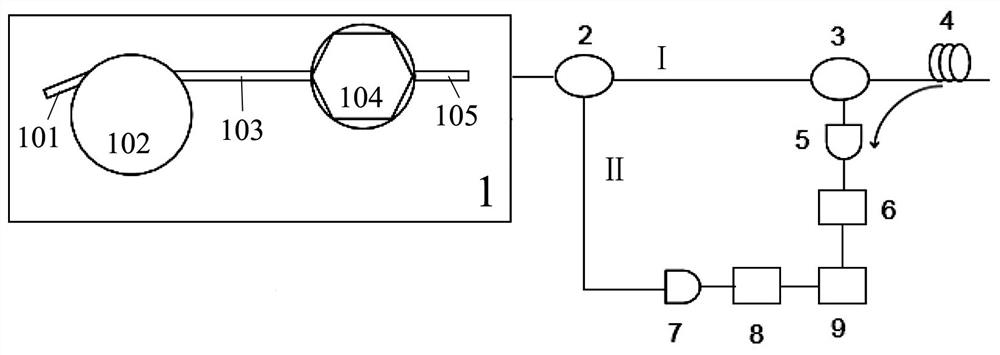
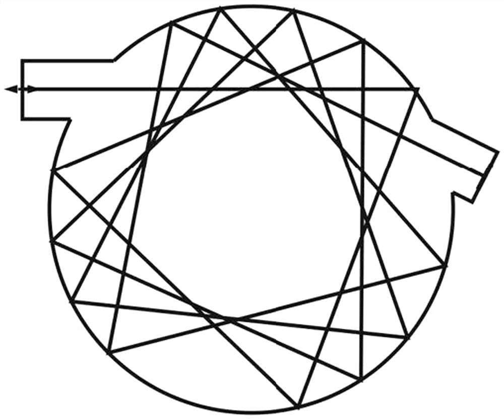
[0016] A high-precision optical fiber fault detection device based on a two-dimensional optical microcavity chaotic laser, such as figure 1As shown: it includes a packaged optical microcavity integrated chaotic laser 1. The optical microcavity integrated chaotic laser 1 includes an arc-shaped hexagonal laser 104 and a deformed microcavity 102. One end of the arc-shaped hexagonal laser 104 passes through a passive waveguide II 103 and One end of the deformed microcavity 102 is connected, and the other end of the deformed microcavity 102 is connected with the passive feedback waveguide 101. I105 is connected, and the passive waveguide I105 in the optical microcavity integrated chaotic laser 1 outputs light to the optical coupler 2, and the optical coupler 2 divides the chaotic laser into two beams, which are probe light I and reference light II respective...


PUM


Abstract

The invention discloses a high-precision optical fiber fault detection device based on a two-dimensional optical microcavity chaotic laser, which comprises a well-packaged optical microcavity integrated chaotic laser. The laser comprises an arc-shaped hexagonal laser and a deformation microcavity, wherein one end of the arc-shaped hexagonal laser is connected with one end of the deformation microcavity through a second passive waveguide, and the other end is connected with a passive feedback waveguide; the end surface of the passive feedback waveguide is plated with a high reflective film; theother end of the arc-shaped hexagonal laser is connected with a first passive waveguide; the first passive waveguide outputs light to an optical coupler; the optical coupler divides the chaotic laserto two beams, respectively, first detection light and second reference light; the first detection light is transmitted to a to-be-detected optical fiber line through an optical circulator, and scattered or reflected echo signals in the line are quantized through a first photodetector and a first ADC and are then inputted to a signal processing device; the second reference light is directly transmitted to be quantized through a second photodetector and a second ADC and are then inputted to the signal processing device; and after cross-correlation processing on the two signals, a fault point isobtained.

Description

technical field [0001] The invention relates to the technical field of photon-integrated chaotic semiconductor lasers, in particular to a high-precision optical fiber fault detection device based on a two-dimensional optical microcavity chaotic laser. Background technique [0002] With the wide application of optical fiber in the field of communication and sensing, optical fiber fault detection device has become an indispensable tool in optical fiber construction detection and fault maintenance. Today's commercial optical fiber fault detection and location methods are based on optical time domain reflectometry, which is a derivative of time domain reflectometer in the optical frequency range. By observing the Rayleigh scattering and Fresnel reflection signals of optical fibers, the detected The signal strength and return time of the optical fiber are used to detect the attenuation characteristics of the optical fiber along the propagation direction, and then detect and judge...

Claims


Application Information

Patent Timeline
Patent Type & Authority Patents(China)
IPC IPC(8): G01M11/00
Inventor 王安帮赵彤王龙生王冰洁王云才
Owner TAIYUAN UNIV OF TECH
Why Eureka
Try Eureka