Automatic device for preparing oil into fuel gas

An automatic device, oil-based technology, used in transportation and packaging, gas and gas/vapor mixing, mixers, etc., can solve the problem of inability to achieve quantitative and fixed ratio mixing of oil and air, inability to effectively prevent reduction to liquid, difficult oil. Problems such as mixing ratio with air, to achieve the effect of omitting heating device, stable pressure, and improving output and quality

Inactive Publication Date: 2019-05-24
山东中沃石油天然气有限公司
View PDF1 Cites 0 Cited by
  • Summary
  • Abstract
  • Description
  • Claims
  • Application Information

AI Technical Summary

Problems solved by technology

The main disadvantages of this device are: 1. The amount of oil consumed by bubbling gasification changes with the change of natural air temperature, and it is impossible to realize quantitative and fixed ratio mixing of oil and air, and the quality of the mixed gas produced is unstable; 2. In the working environment with low temperature, the oil and gas in the light hydrocarbon mixed air gas will be reduced to a liquid state; 3. In the process of gas production, a large amount of oil is stored in the reactor, which has serious safety hazards; 4. Raw materials for gas production Only C5 with high purity can be used, with a specific gravity of 0.62. It is difficult to gasify oil with a specific gravity of 0.63-0.69 to make gas, and the cost remains high; need
Its disadvantages are: 1. It is difficult to stabilize the mixing ratio of oil and air by using the principle of bubbling to gasify light hydrocarbon oil; 2. The electric constant temperature device is only used to heat the oil, and the air participating in the bubbling is not constant temperature, which cannot effectively prevent the gas from meeting When the air is cold, the oil and gas in it are reduced to a liquid state; 3. Light hydrocarbon oil is a flammable and dangerous product. The main gas-making device is installed in the raw material storage tank, and there is no need between the electric heating device and the mechanical movement device and the oil storage tank. There is a serious safety hazard

Method used


Image

  • Automatic device for preparing oil into fuel gas

Examples


Embodiment Construction

[0021] The preferred embodiments of the present invention will be described in detail below in conjunction with the accompanying drawings, so that the advantages and features of the present invention can be more easily understood by those skilled in the art, so as to define the protection scope of the present invention more clearly.

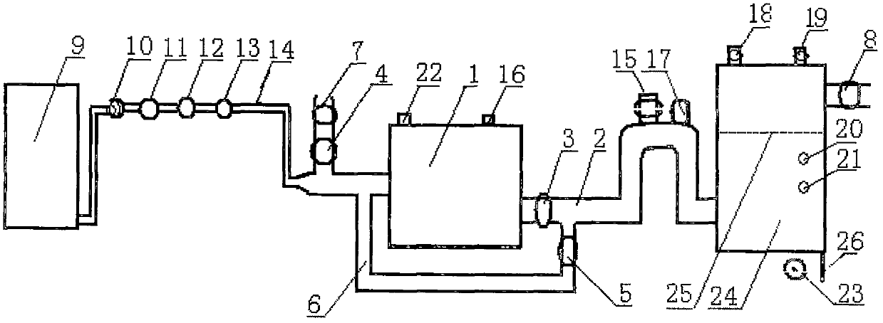
[0022]An oil-to-gas automatic device, comprising: a high-pressure blower 1, a delivery pipeline 2, a check valve 3, an air flow meter 4, a pressure relief diverter valve 5, a diverter feedback pipe 6, an air flow regulator 7, a gas switch 8, a gas storage Oil tank 9, oil valve 10, flow regulator 11, solenoid valve 12, flow meter 13, oil delivery pipe 14, automatic pressure control switch 15, automatic fan temperature control switch 16, automatic gas temperature control switch 17, safety valve 18, vent solenoid Valve 19, overpressure alarm 20, overtemperature alarm 21, fan temperature alarm switch 22, leakage alarm 23, buffer tank 24, anti-static n...


PUM


Abstract

The invention discloses an automatic device for preparing oil into fuel gas. The automatic device comprises a high-pressure fan, a pressure relief flow divider valve, a flow dividing feedback tube, anoil storage tank, an oil conveying pipe, a flow adjustor, a pressure automatic control switch and a temperature automatic control switch, the pressure relief flow divider valve is installed at an outlet of the high-pressure fan, overpressure overflowing gas returns into a suction port of the high-pressure fan through the flow dividing feedback tube, the oil conveying pipe is connected with an outlet of the oil storage tank and the suction port of the high-pressure fan, and the flow adjustor, the pressure automatic control switch and the temperature automatic control switch control the flow, pressure and temperature in a gas-preparing technological process respectively. In this way, an oil conveying pump, a reaction kettle and a heating device are omitted, the manufacturing cost for the device is lowered, the oil with the specific gravity being 0.62-0.69 can be prepared into the fuel gas, energy saving and emission reduction are realized for an enterprise, and funds are saved for the enterprise.

Description

Technical field: [0001] The invention introduces an automatic oil-to-gas device, which is mainly used to improve the existing gas-to-gas process of light hydrocarbon mixed with air, and to provide high-quality, cheap, clean and safe gas for industrial and civil use. Background technique: [0002] The raw material for oil-to-gas is light hydrocarbon light oil, with a specific gravity of 0.62-0.69, which is liquid at room temperature. After gasification, it is mixed with air to make light hydrocarbon-air mixed gas. The existing light hydrocarbon gas gas production process is mainly to place light hydrocarbon oil (C5, i.e. carbon five, specific gravity 0.62) in a reaction kettle or a storage tank for gasification after blowing, and mix it with air at the same time to form a combustible gas . In the Chinese patent literature, there is "A High-Energy Mixed Light Hydrocarbon Gas Reactor" (patent application number: CN201520658405.4), its main feature is that light hydrocarbon oil...

Claims


Application Information

Patent Timeline
Patent Type & Authority Applications(China)
IPC IPC(8): B01F3/02B01F5/12B01F15/00B01F15/04B01F23/10B01F25/60
Inventor 王培林柯金筑
Owner 山东中沃石油天然气有限公司
Why Eureka
Try Eureka