

Lubrication system of handheld air-cooled four-stroke gasoline engine and gasoline engine
A lubricating system and gasoline engine technology, applied in the direction of engine lubrication, pressure lubricant, machine/engine, etc., can solve the problems of increasing the manufacturing cost of the whole machine, losing the function of the oil-gas separation mechanism, and affecting the performance of the gasoline engine, so as to ensure stability, Lubricating oil forms the effect of reliable circulation separation and simple structure
- Summary
- Abstract
- Description
- Claims
- Application Information
AI Technical Summary
Problems solved by technology
Method used
Image

Examples
Embodiment Construction
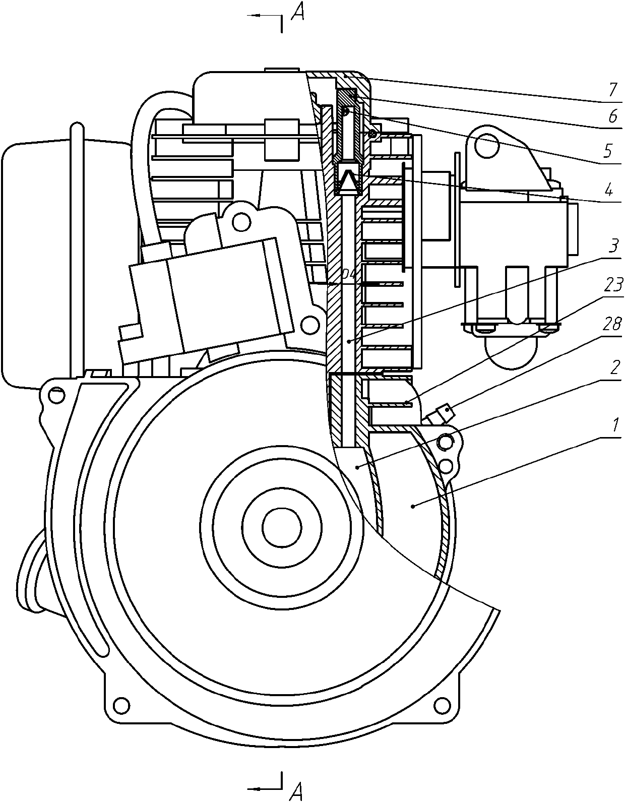
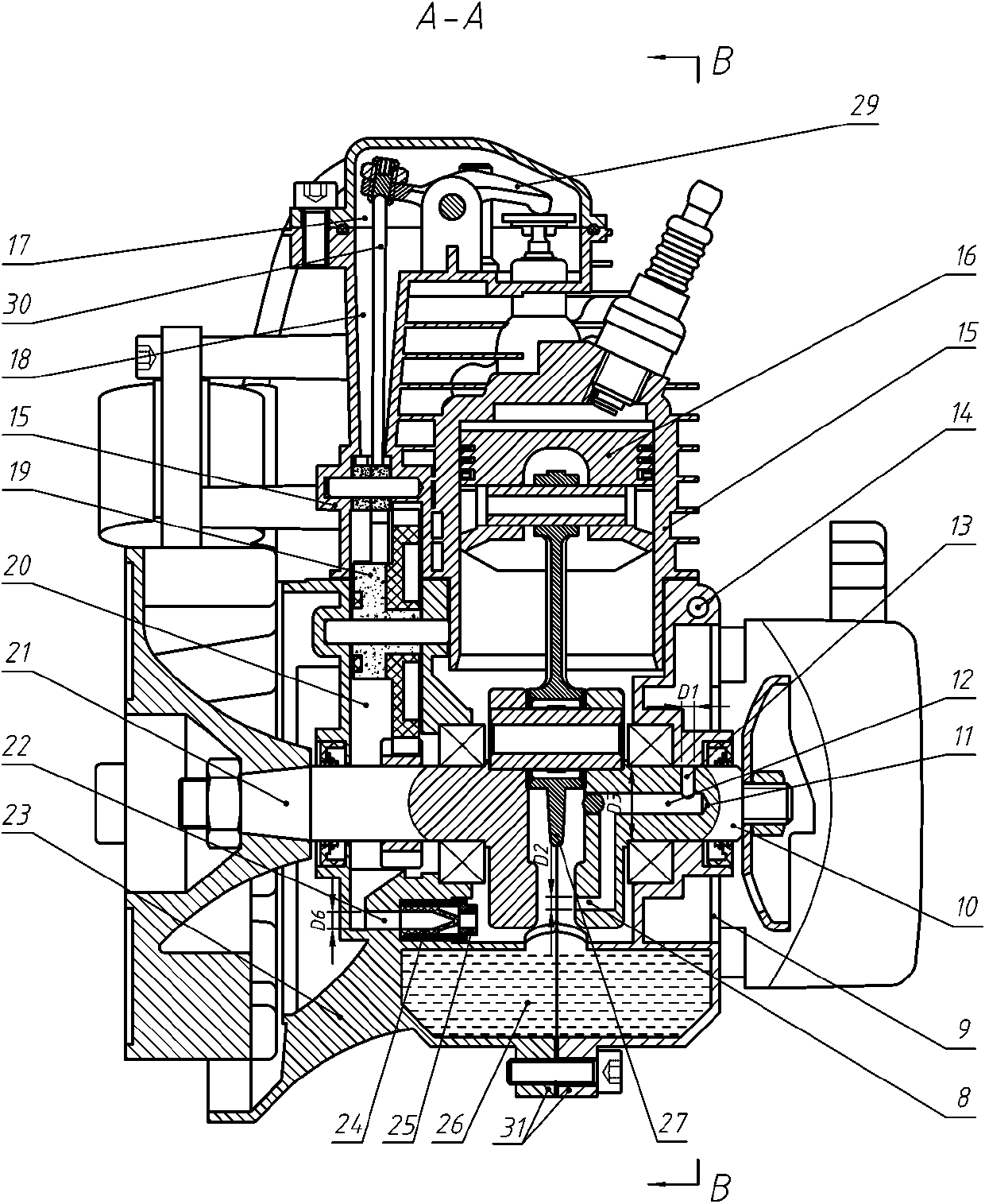
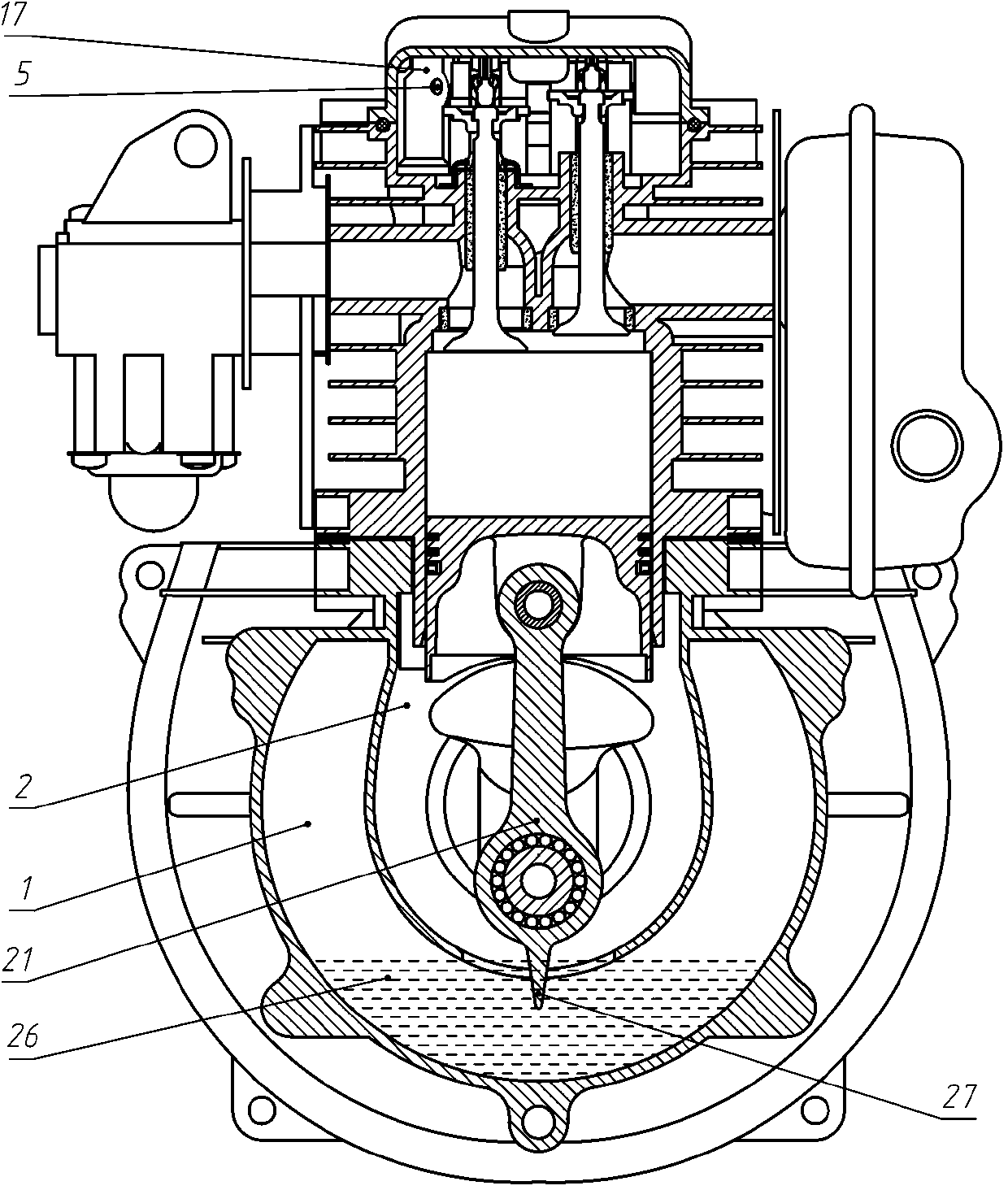
[0040] Such as Figure 1 to Figure 7As shown, a hand-held air-cooled four-stroke gasoline engine lubrication system is divided into interconnected crankshaft chamber 2, oil storage chamber 1, and primary oil-gas separation channel 11 (including crankshaft connecting rod group 21, rear half crankshaft, etc.) 10. Air intake hole 8, oil-gas separation channel 12 and air outlet hole 13), secondary exhaust channel 32 (including oil-gas separation channel 12, air outlet hole 13, and exhaust hole 28), oil upper channel 3 (including the front half crankcase 23. Cylinder block 15, oiling check valve 4, oiling check valve seat 6, squeeze hole 5), oil return passage (including valve chamber 17, tappet chamber 18, cam assembly 19, oil return passage 22, return Oil check valve 24, oil return check valve seat 25).
[0041] A lubricating oil passage 14 is provided on the rear half crankcase 9, and the lubricating oil passage 14 communicates with the oil storage chamber 1 to form a lubricati...
PUM
 Abstract
Description
Claims
Application Information