Ultra-long gravity heat pipe geothermal extraction device with steam-water separation

A technology of steam-water separation device and gravity heat pipe, which is applied in the direction of geothermal energy, separation method, geothermal energy power generation, etc., and can solve the problems of inability to make unpowered auxiliary heat pipes, reduce system efficiency, and increase system power consumption

Active Publication Date: 2021-01-08
GUANGZHOU INST OF ENERGY CONVERSION - CHINESE ACAD OF SCI
View PDF7 Cites 1 Cited by
  • Summary
  • Abstract
  • Description
  • Claims
  • Application Information

AI Technical Summary

Problems solved by technology

Collecting heat requires a certain amount of power consumption, increasing system power consumption and reducing system efficiency
Due to the characteristics of the heat pipe itself, there are heat transfer limits such as the carrying limit and the capillary limit, and there is a transmission length limit, so it is impossible to make an unpowered auxiliary heat pipe that is too long

Method used


Image

  • Ultra-long gravity heat pipe geothermal extraction device with steam-water separation
  • Ultra-long gravity heat pipe geothermal extraction device with steam-water separation
  • Ultra-long gravity heat pipe geothermal extraction device with steam-water separation

Examples


Embodiment 1

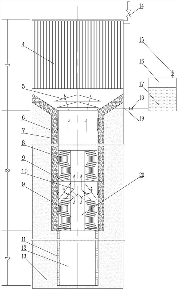
[0034] figure 1 It is a schematic diagram of the device of Example 1 of the present invention. The heat extraction section 3 of the ultra-long gravity heat pipe with steam-water separation directly reaches the bottom of the geothermal well 13 , and the geothermal energy of the geothermal well 13 is transferred to the heat extraction section 3 . Some heat conduction fillers can be filled between the heat extraction section 3 and the geothermal well 13 to increase the heat transfer effect. The working medium liquid contained in the porous core layer 11 on the wall surface of the heating section 3 is heated and evaporated to generate working medium vapor. The liquid-laden vapor rises to adiabatic section 2. A steam-water separation device is installed at the junction of the heat insulation section 2 and the heat extraction section 3 . An air duct 20 and a baffle 9 are arranged in the middle of the inlet of the steam-water separation structure. The steam is divided into two pa...

Embodiment 2

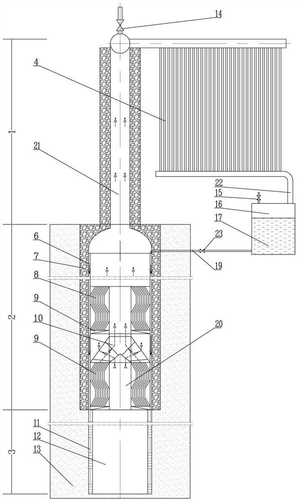
[0037] figure 2It is a schematic diagram of the device of Example 2 of the present invention. The heat extraction section 3 of the ultra-long gravity heat pipe with steam-water separation directly reaches the bottom of the geothermal well 13 , and the geothermal energy of the geothermal well 13 is transferred to the heat extraction section 3 . Some heat conduction fillers can be filled between the heat extraction section 3 and the geothermal well 13 to increase the heat transfer effect. The working medium liquid contained in the porous core layer 11 on the wall surface of the heating section 3 is heated and evaporated to generate working medium vapor. The liquid-laden steam rises to the adiabatic section 2, and a steam-water separation device is installed at the junction of the adiabatic section 2 and the heat extraction section 3. An air duct 20 and a baffle 9 are arranged in the middle of the inlet of the steam-water separation structure. The steam is divided into two pa...


PUM


Abstract

The invention discloses an ultra-long gravity heat pipe geothermal mining device with a steam-water separation function. A steam-water separation device is arranged between a heat taking section and aheat insulating section, thus the liquid carrying amount of ascending working medium steam is greatly decreased, and the air flow speed is decreased; in addition, descending liquid is collected through a flow guiding plate structure and the like, and thus intersection of ascending gas and descending gas is avoided; and meanwhile, the density difference of the ascending steam and the descending working medium liquid is increased, driving force is increased because of increase of the working medium liquid density difference to be sufficient to overcome increased resistance of the steam-water separation device, and thus the capability of pipe heat length conveying is improved.

Description

technical field [0001] The invention relates to the technical field of geothermal exploitation, in particular to an ultra-long gravity heat pipe geothermal exploitation device with steam-water separation. Background technique [0002] Geothermal heat is the heat energy generated by long-lived radioactive isotope thermonuclear reactions in the earth's interior, which is transmitted to the earth's crust through the high-temperature magma in the mantle. This deep geothermal energy source is inexhaustible and inexhaustible. This kind of geothermal energy generally exists in the following layers of different temperatures from the outside to the core: the outer thermosphere affected by the atmospheric environment and solar radiation on the surface of the earth’s crust, and the lower boundary of the outer thermosphere, where the temperature does not change at a certain depth Normal temperature layer: Below the normal temperature layer, due to the influence of the earth's internal h...

Claims


Application Information

Patent Timeline
Patent Type & Authority Patents(China)
IPC IPC(8): F28D15/02F24T10/10F24T10/40B01D53/26
CPCY02E10/10
Inventor 杨卫斌汪小憨曾小军
Owner GUANGZHOU INST OF ENERGY CONVERSION - CHINESE ACAD OF SCI
Why Eureka
Try Eureka