
Biogas generation system and production technology

A technology for generating system and biogas, which is applied in the fields of gas production bioreactor, biological sludge treatment, waste fuel, etc., can solve the problems of low mixing degree of raw material and biogas slurry, poor mixing uniformity of raw material, low working efficiency, etc. The effect of improving equipment utilization, improving gas production efficiency and high work efficiency

Active Publication Date: 2019-05-28
方旭华
View PDF8 Cites 1 Cited by
  • Summary
  • Abstract
  • Description
  • Claims
  • Application Information

AI Technical Summary

Problems solved by technology

[0007] The purpose of the present invention is to overcome the defects and problems of low working efficiency, low mixing degree of raw materials and biogas slurry, poor mixing uniformity between raw materials and low gas production efficiency existing in the prior art, and provide a working A biogas generation system and production process with high efficiency, high mixing degree of raw materials and biogas slurry, good mixing uniformity between raw materials, and high gas production efficiency

Method used


Image

  • Biogas generation system and production technology
  • Biogas generation system and production technology
  • Biogas generation system and production technology

Examples


Embodiment 1

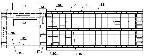
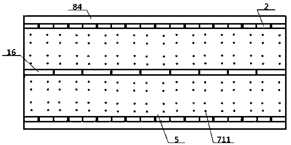
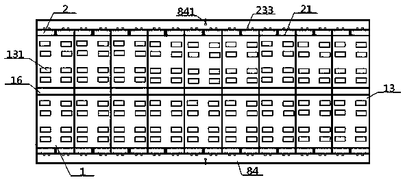
[0061] see Figure 1 to Figure 13 , a biogas generation system, including a raw material workshop 9 and a fermentation workshop 90, the raw material workshop 9 includes a manure stacking area 91 and a straw stacking area 92, and the fermentation workshop 90 includes a stacking board 5, a biogas tank 1 and an outer cover 98, An outer cover 98 is covered above the stockpiling plate 5, and a biogas digester 1 is arranged below the stockpiling plate 5, and both sides of the biogas digester 1 communicate with a feed channel 2; the raw material workshop 9 includes end-to-end loading Track 93, steering track 94, horizontal return track 95, vertical return track 96, the loading track 93 is sandwiched between the manure stacking area 91 and the straw stacking area 92, and the lateral direction of the horizontal return track 95 and the stacking The boards 5 communicate with each other, and a plurality of parking spaces 51 are arranged on the top surface of the stacking board 5; the feed...

Embodiment 2

[0065] Basic content is the same as embodiment 1, the difference is:

[0066]A dodge door 3 is arranged in the described feed inlet 22, and the top of this dodge door 3 contacts with the top edge of feed inlet 22, and the bottom end of dodge door 3 is hinged with the bottom edge of feed inlet 22, and movable The side portion of door 3 is oppositely arranged with outer road wall 23, and the top of outer road wall 23 is connected with the inner end of transverse platform 24, and the top surface of transverse platform 24 is in contact with the bottom of pressing side pusher 4, and presses down. One end near the feed channel 2 on the side pusher 4 is provided with an inner push rod 43 and an outer push rod 44. It is set directly opposite, and the fermentation chamber 14 communicates with the feed channel 2 through the movable door 3 . The push-down side pusher 4 includes a base 41 and a binder block 42 connected thereon, an inner push rod 43, an outer push rod 44, an inner cylind...

Embodiment 3

[0068] Basic content is the same as embodiment 1, the difference is:

[0069] The biogas generation system also includes a vibrating screen 7, the vibrating screen 7 includes a vibrating vertical shaft 71 and a vibrating grid plate 72, and the vibrating grid plate 72 is provided with a plurality of grid plate through holes 721; No. assembly vertical side 73, No. 1 supporting horizontal side 731, No. 2 assembling vertical side 732, No. 2 supporting horizontal side 733, No. 1 assembling vertical side 73, No. 2 assembling vertical side 732 facing each other, No. 1 supporting horizontal side 731 1. The No. 2 supporting horizontal edge 733 is set oppositely, and the No. 1 assembling vertical edge 73 and the No. 2 assembling vertical edge 732 are respectively embedded with an I-shaped beam 74 on the front and rear ends of the respective inner walls. The upper beam in the I-shaped beam 74 The plate 741 and the lower beam plate 742 are exposed in the air vent 131, and the four lower b...


PUM


Abstract

The invention relates to a biogas generation system. The biogas generation system comprises a raw material workshop and a fermenting workshop, wherein the raw material workshop comprises a loading rail, a steering rail, a transverse return rail and a vertical return rail which are connected in a head-to-tail way; the fermenting workshop comprises a material stacking plate, a biogas tank and an outer cover; the biogas tank comprises a left inclined bottom casing, a right inclined bottom casing, a top plate of the biogas tank and a fermenting cavity; the inner ends of the left inclined bottom casing and right inclined bottom casing are connected; the outer ends of the left inclined bottom casing and right inclined bottom casing are connected with the top plate of the biogas tank through a material inlet and an upper wall passage of the material inlet; the heights of the left inclined bottom casing and right inclined bottom casing are gradually increased from the inner ends to the outer ends; a biogas accommodation cavity is clamped between the top plate of the biogas tank and the material stacking plate; the fermenting cavity is communicated with the biogas accommodation cavity through a gas ventilating port; a slag intake passage is arranged at the middle parts of the top plate of biogas tank and the material stacking plate and just vertically faces the crossing part of the leftinclined bottom casing and right inclined bottom casing. By adopting the design, the biogas generation system has the advantages that the mixing degree of biogas slurries is high, the mixing uniformity between the raw materials is better, the working efficiency and biogas production efficiency are higher, the interference between the slag intake and biogas production is avoided, and the slag intake efficiency is higher.

Description

technical field [0001] The invention relates to a biogas production technology, which belongs to the field of biogas fermentation, and in particular to a biogas generation system and a production process, which are specifically suitable for improving work efficiency, increasing the mixing uniformity between raw materials and biogas liquid, and between raw materials, and improving Gas production efficiency. Background technique [0002] With the development of my country's agriculture, the amount of straw waste produced is increasing, and random waste or burning of straw will easily pollute the environment. Therefore, it has become a consensus to use straw for biogas fermentation. At present, the fermentation raw materials used in most biogas projects in China are in the liquid state of poultry manure. Therefore, most of the feeding devices used are liquid pumps. This type of feeding device limits the solid content to 5%. The particle size is about 2 cm. If the pure straw ra...

Claims


Application Information

Patent Timeline
IPC IPC(8): C12M1/107C12P5/02C02F11/04
CPCY02E50/30
Inventor 方旭华
Owner 方旭华
Learn More