Method for quantitatively reconstructing complex boundary contour of interlayer debonding defect based on infrared detection image signal

An infrared detection and image signal technology, applied in image analysis, image data processing, material defect testing, etc., to achieve the effect of improving reconstruction efficiency, small amount of data, and efficient quantitative reconstruction efficiency

Active Publication Date: 2019-05-28
XI AN JIAOTONG UNIV
View PDF6 Cites 6 Cited by
  • Summary
  • Abstract
  • Description
  • Claims
  • Application Information

AI Technical Summary

Problems solved by technology

[0004] In order to solve the quantitative problem of complex debonding defects in the above-mentioned existing multilayer welding materials, the purpose of the present invention is to provide a method for quantitatively reconstructing the complex boundary contours of interlayer debonding defects based on infrared detection image signals, which can complete the multilayer Accurate quantification of the two-dimensional boundary profile of debonding defects in welding materials has the advantages of simple operation, easy realization, good adaptability, high efficiency, and is suitable for complex debonding defects. It can be widely used in the middle layer of mechanical structures such as military industry and nuclear power Quantitative evaluation of disbond defects between

Method used


Image

  • Method for quantitatively reconstructing complex boundary contour of interlayer debonding defect based on infrared detection image signal
  • Method for quantitatively reconstructing complex boundary contour of interlayer debonding defect based on infrared detection image signal
  • Method for quantitatively reconstructing complex boundary contour of interlayer debonding defect based on infrared detection image signal

Examples


Embodiment Construction

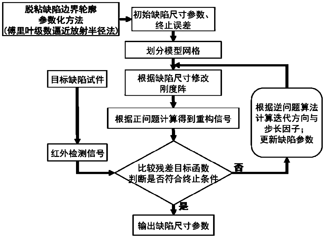
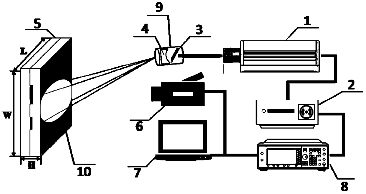
[0045] Such as figure 1 Shown is the quantitative reconstruction flow chart of the complex boundary contour of the debonding defect between the layers of the multi-layer material of the present invention. Firstly, the multi-layer material specimen containing the debonding defect is made, and then the experimental measurement is carried out by using the self-built laser infrared non-destructive testing experimental system. The transient temperature signal on the upper surface of the specimen in the disbonding defect area is obtained and the differential temperature change rate signal is calculated. Secondly, based on the control equation of the transient temperature field, the infrared detection finite element program is written to calculate the transient temperature signal of the simulation numerical model of the test piece. For the debonding complex boundary contour, the Fourier series approximation radiation radius method is used for parametric description . Development of ...


PUM


Abstract

The invention relates to a method for quantitatively reconstructing a complex boundary contour of an interlayer debonding defect based on an infrared detection image signal, which comprises the following steps of: firstly, building an infrared thermal imaging temperature field measuring system, processing and manufacturing a multilayer structure flat plate test piece containing the debonding defect; then measuring a transient temperature signal of an upper surface area of the flat plate test piece by using the built infrared detection system, and calculating a differential temperature variablerate signal image as a reconstruction characteristic signal; and secondly, based on a simulation calculation method of a transient temperature field numerical model and a defect reconstruction inverse algorithm, providing a parameterization method of the debonding defect complex boundary contour of a Fourier series approximation radial method so as to achieve efficient and accurate quantitative nondestructive evaluation of the debonding defect complex boundary contour of the multilayer structure. The method can efficiently and accurately reconstruct the boundary contour of the debonding defect, has the advantages of simple principle, convenient and easy operation, small data volume, high quantitative efficiency and the like, and can be widely applied to quantitative evaluation of the interface debonding defect of multilayer welding mechanisms in nuclear power and chemical industry.

Description

technical field [0001] The invention relates to a method for quantitatively reconstructing the complex boundary of debonding defects, in particular to a method for quantitatively reconstructing the complex boundary contour of interlayer debonding defects based on infrared detection image signals. Background technique [0002] Non-destructive testing technology is the key technology to ensure the manufacturing quality and operation safety of major engineering equipment. Due to its special structure and performance, multilayer metal welding materials are widely used in key heat conduction and protection components in nuclear power equipment. During the long-term service of this material, due to the load of high radiation and high heat flow, interlayer cracking and debonding defects appear at the welding interface, which often leads to heat accumulation, melting and radiation leakage of key structural components of nuclear power plants. It is highly concealed and harmful. Regu...

Claims


Application Information

Patent Timeline
Patent Type & Authority Applications(China)
IPC IPC(8): G01N25/72G06T7/00G06F17/50
Inventor 陈振茂刘皓晨解社娟裴翠祥李勇
Owner XI AN JIAOTONG UNIV
Why Eureka
Try Eureka