
Indoor heating system of wall-mounted furnace coupling heat exchanger

A technology for heating systems and wall-hung boilers, applied in electric heating systems, heating systems, heat storage heaters, etc., can solve the problems of large power consumption, excessive peak-to-valley difference in power grid load, and high manufacturing costs, and achieve expansion and replacement Thermal area, the effect of prolonging the process

Inactive Publication Date: 2019-05-31
杨斯涵
View PDF0 Cites 3 Cited by
  • Summary
  • Abstract
  • Description
  • Claims
  • Application Information

AI Technical Summary

Problems solved by technology

In winter in hot summer and cold winter regions, the heating equipment used by people is mainly electric heating, including air conditioners, water heating radiators, electric oil heaters, electric quartz tube heaters, carbon fiber Yuba, electric heating ceramic heating heaters, but these heating The equipment is heated by electricity, and the power consumption is large, and the cost of heating is not ideal
In recent years, the world's economically developed countries have had the problem of excessive peak-to-valley differences in power supply networks, which hinders the rational use of power resources and affects the effective development of electric heating equipment. In addition, the existing air-conditioning heating consumes a lot of power. The manufacturing cost is high, and there are some problems in the process of installation and use. For example, the outdoor unit will transfer a large amount of heat to the environment during use, which does not meet the requirements of energy saving and emission reduction. To sum up, the existing household heating equipment uses The time consumption of electricity is large, and some electric heating devices use the heating time at the same time as the electric heating time when the overall power grid load reaches its peak value, which will exacerbate the problem of excessive peak-valley load difference of the power grid

Method used


Image

  • Indoor heating system of wall-mounted furnace coupling heat exchanger
  • Indoor heating system of wall-mounted furnace coupling heat exchanger
  • Indoor heating system of wall-mounted furnace coupling heat exchanger

Examples


Embodiment Construction

[0027] Below in conjunction with accompanying drawing, the present invention will be further described:

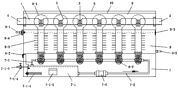
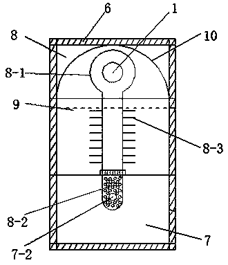
[0028] Such as figure 1 , figure 2 As shown, the present invention is an indoor heating system for a wall-hung furnace coupled with a heat exchanger. The indoor heating system includes a heat exchanger assembly and a wall-hung furnace assembly; 2. Heat transfer finned tube 3, air intake pipe 4 and exhaust pipe 5, wherein the air intake pipe is connected to the inlet end of the heat exchange pipe, and the exhaust pipe is connected to the exhaust port of the heat exchange pipe; on the heat exchange pipe A number of heat exchange sections are arranged in an orderly manner, and two symmetrical and concentric round holes are arranged at the heat exchange section. The convex surface of the semicircular heat transfer fin is embedded in the two round holes on the heat exchange pipe and sealed There is no leakage in the connection; there are several heat transfer fin tubes with ...


PUM


Abstract

The invention discloses an indoor heating system of a wall-mounted furnace coupling heat exchanger. The indoor heating system comprises a heat exchanger assembly and a wall-mounted furnace assembly. The heat exchanger assembly comprises a heat exchange pipeline, a semi-arc heat transfer fin, a heat transfer fin tube, a gas inlet pipeline and an exhaust pipeline. A plurality of heat exchange sections are orderly arranged on the heat exchange pipeline. The wall-mounted furnace assembly comprises a wall-mounted furnace shell, a heat storage cavity and a heat exchange cavity, wherein the heat storage cavity and the heat exchange cavity are sequentially arranged in the wall-mounted furnace shell from bottom to top. A heater and a heat accumulator are arranged in the heat storage cavity. The heat exchange pipeline and a plurality of heat transfer structures which are arranged in order corresponding to the heat exchange sections are arranged in the heat exchange cavity. The heat transfer structures absorb heat from the heat storage cavity and then exchange heat with the heat exchange sections in the heat exchange cavity. Therefore, cold air in the heat exchange pipeline can be heated. Bymeans of the indoor heating system of the wall-mounted furnace coupling heat exchanger, heat can be stored during slack hours of electric power supply and can be released during peak hours of electricity consumption, so that peak hour shaving is realized. In addition, the system is fast in heat storage, heat transfer, heating and heat supply and high in heat energy utilization rate, saves energy and protects the environment.

Description

technical field [0001] The invention relates to the technical field of wall-hung boiler heating, in particular to an indoor heating system in which a wall-hung boiler is coupled with a heater. Background technique [0002] With the gradual growth of my country's economy, people's material and cultural living standards have been significantly improved, and the living conditions of residents are improving day by day. People's requirements for the comfort and health of the home environment are getting higher and higher. my country's construction industry, especially The rapid development of the housing industry has led to the rapid growth of the production of household air conditioners; household heating and cooling equipment have been widely used in both urban and rural areas. occupy a considerable share of the volume. At present, resource and energy problems and environmental pollution problems are becoming more and more serious. How to effectively and reasonably allocate and ...

Claims


Application Information

Patent Timeline
IPC IPC(8): F24H7/02F24H9/00F24H9/18F24H9/20F24D13/04F24D15/02
Inventor 杨斯涵
Owner 杨斯涵
Features
  • Generate Ideas
  • Intellectual Property
  • Life Sciences
  • Materials
  • Tech Scout
  • Unparalleled Data Quality
  • Higher Quality Content
  • 60% Fewer Hallucinations
Learn More