Wind profiler radar based on interference algorithm

A wind profile radar and algorithm technology, applied in the field of wind profile radar, can solve the problems of short detection period, long detection period, large weight and volume, etc., and achieve the effects of excellent performance, simplified manufacturing cost, and simple equipment

Active Publication Date: 2019-05-31
南京微麦科斯电子科技有限责任公司
View PDF11 Cites 2 Cited by
  • Summary
  • Abstract
  • Description
  • Claims
  • Application Information

AI Technical Summary

Problems solved by technology

[0006] In order to overcome the disadvantages of complex process, large weight and volume, high price, and long detection period in the prior art when measuring below the boundary layer, the purpose of the present invention is to provide a wind profile radar based on an interferometric algorithm. When the line radar measures below the boundary layer, it has the characteristics of simple process, small weight and volume, low price and short detection period

Method used


Image

  • Wind profiler radar based on interference algorithm
  • Wind profiler radar based on interference algorithm
  • Wind profiler radar based on interference algorithm

Examples


Embodiment 1

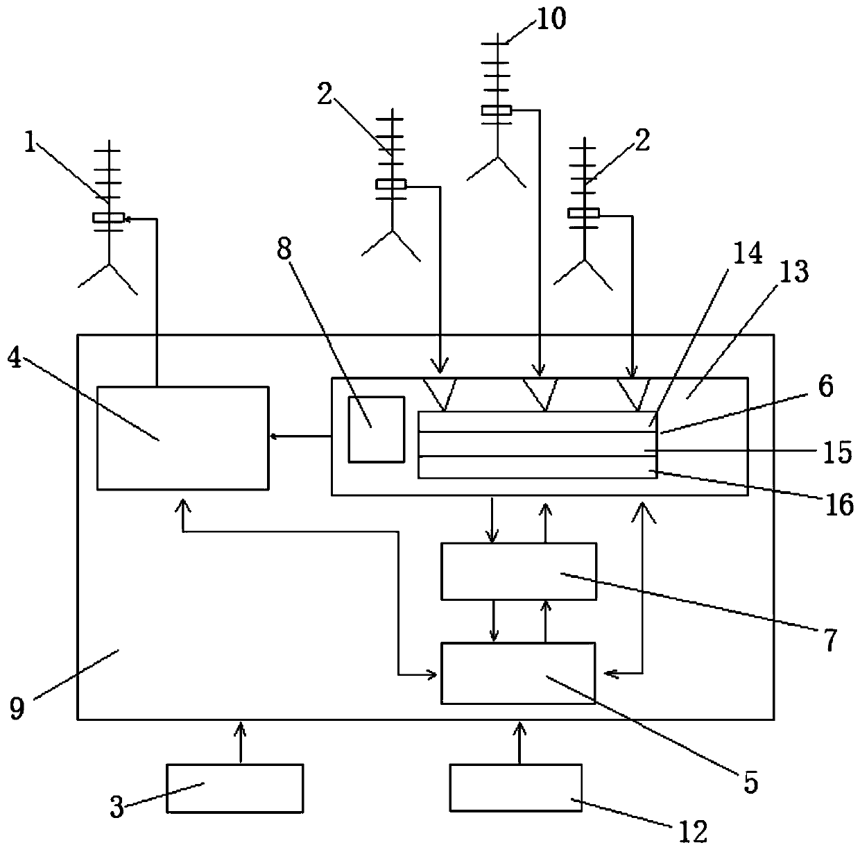
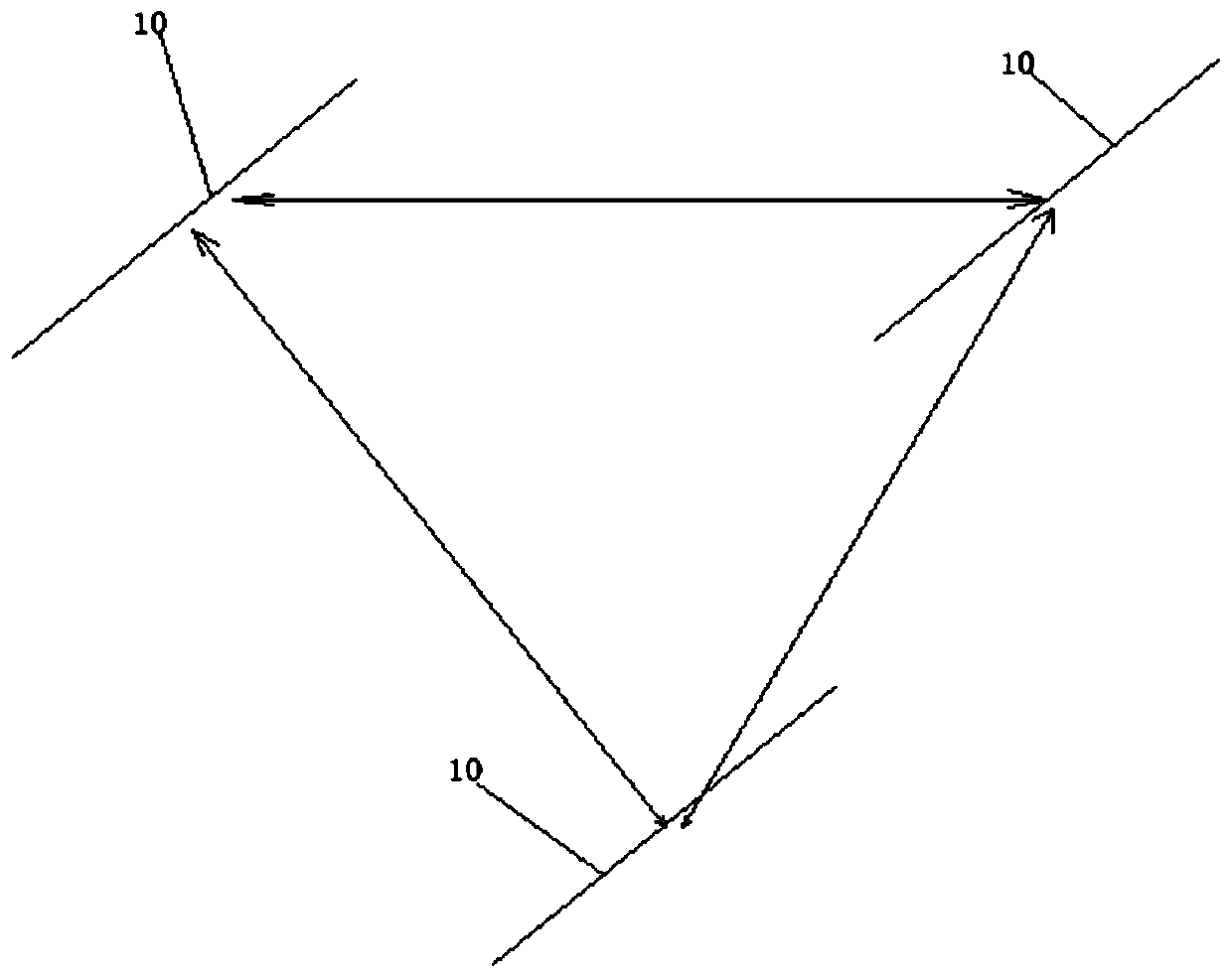
[0053] Such as figure 1 , figure 2 As shown, a wind profile radar based on an interferometric algorithm, the wind profile radar works in the P-band; includes a transmitting antenna 1, a receiving antenna 2, an integrated cabinet 9, a power module 3 and a communication module 12. Wherein, the integrated chassis 9 includes a transmitter 4 , a receiver 6 , a signal processing unit 7 , and a data processing unit 5 . The wind profiler radar is installed perpendicular to the ground, emits electromagnetic waves upwards, measures the parameters of the wind from the ground to more than 1km, and outputs the horizontal wind direction, horizontal wind speed, vertical wind speed, and vertical wind direction distributed according to height.

[0054] Further, when the radar is working, firstly, the data processing unit 5 controls the signal processing unit according to the determined working mode, and the signal processing unit 7 controls the frequency source of the receiver 6 to generate a ...

Embodiment 2

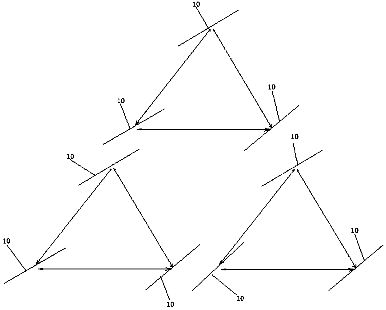
[0097] In this embodiment, the number of receiving antennas is 9, such as image 3 As shown, the spacing between the antenna elements in the three antenna groups is still 0.7λ, and the spacing is 0.5m. The distance between the three groups is 1.3λ, and the distance is 0.92m. Other content of this embodiment is the same as that of Embodiment 1, and will not be repeated here.

Embodiment 3

[0099] The number of receiving antennas in this embodiment is 27, which are not shown in the figure, and the spacing between the antenna elements in the three antenna groups is still 0.7λ, and the spacing is 0.5m. The distance between the three groups is 2.0λ, and the distance is 1.4m. Since the area of ​​the antenna array is relatively large, the receiving antenna array and the transmitting antenna array can share one. Other content of this embodiment is the same as that of Embodiment 1, and will not be repeated here.


PUM


Abstract

The invention provides a wind profiler radar based on an interference algorithm. The radar comprises a transmitting antenna and multiple groups of receiving antennas. The transmitting antenna is independently arranged, and each group of the receiving antennas is arranged in a triangle. Echo signals received by each group of antennas are orthogonally sampled to obtain I and Q orthogonal signals. Instep (1), two horizontal components of an atmospheric turbulent moving speed are obtained by using an interference algorithm. In step (2), a Doppler effect is obtained by using Fourier transform processing, and the vertical velocity and direction of atmospheric turbulence are obtained. According to the invention, the processing is carried out by using phase information of the signals, a beam doesnot need to be scanned, the time period of wind field acquisition is obviously shortened and is only 20% of the time period of an existing wind profile radar, since the beam does not need to be scanned, a beam control system of an existing wind profile and a larger number of phase shifters are not needed, the manufacturing cost of the antennas is reduced, and the installation requirements of theantenna are reduced.

Description

technical field [0001] The invention belongs to the technical field of measuring wind in meteorological detection, and relates to a wind profile radar based on an interference algorithm. Background technique [0002] Wind profiler radar is a remote sensing device for high-altitude wind field detection by transmitting electromagnetic beams to high altitudes, receiving and processing the information returned by the electromagnetic beams due to the uneven vertical structure of the atmosphere. Wind profiler radar has become an effective tool for continuous and real-time remote sensing of atmospheric wind field. It is especially suitable for occasions that require spherical wind measurement, such as airports and paratrooper training. It can meet requirements such as airport wind measurement equipment network deployment and important facility meteorological support. need. [0003] Wind profiler radar can detect the changes of meteorological elements such as wind direction and win...

Claims


Application Information

Patent Timeline
Patent Type & Authority Applications(China)
IPC IPC(8): G01S13/95
CPCY02A90/10
Inventor 张越林思夏曾仲毅
Owner 南京微麦科斯电子科技有限责任公司
Why Eureka
Try Eureka