

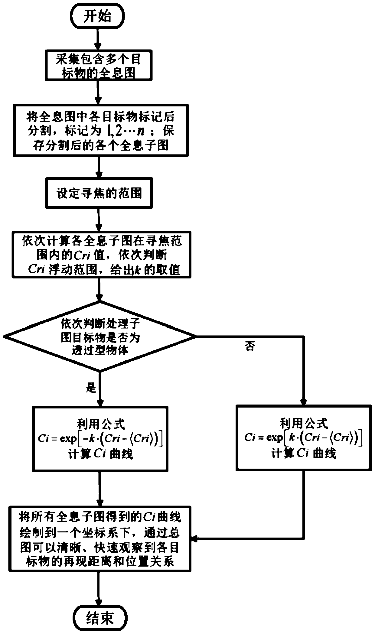
Autofocus method for multi-object digital holographic measurement
A digital holographic and auto-focusing technology, applied in installation, optics, instruments, etc., can solve the problems of submerged target focusing, difficult to distinguish, and the peak of the focus curve is not obvious, so as to improve the reproduction distance discrimination speed and discrimination ability, and improve accuracy and real-time performance, reducing the difficulty of peak identification
- Summary
- Abstract
- Description
- Claims
- Application Information
AI Technical Summary
Problems solved by technology
Method used
Image

Examples
Embodiment
[0050] Combine below Figure 2 to Figure 4 The present invention is described in detail. It should be noted that the embodiments described here are only used to explain the present invention, but not to limit the present invention. In addition, the technical features involved in the present invention described below can be combined with each other as long as they do not conflict with each other.
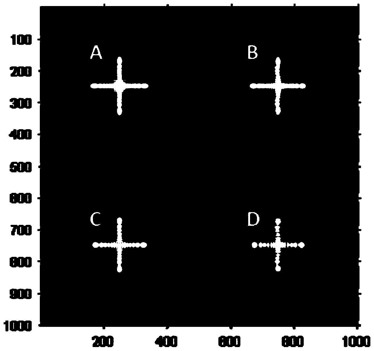
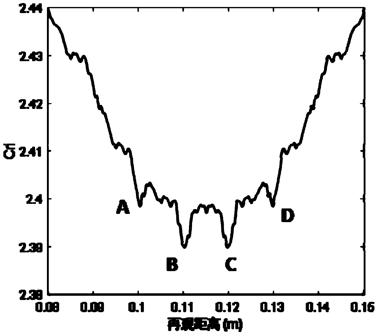
[0051] The cross-shaped transparent target is selected in the simulation. There are four targets marked as A, B, C, and D. The distance from the receiving surface is set to 10cm, 11cm, 12cm and 13cm. The calculated hologram is as follows figure 2 Shown. will figure 2 The shown hologram containing all the targets is calculated by the traditional auto-focus algorithm and obtained as image 3 The focus curve shown in the figure is not easy to find the specific position of the target, which increases the difficulty of identification and affects the speed of the middle and post-processing...
PUM
 Abstract
Description
Claims
Application Information