Laser collimation structure and product using the same

A laser collimation and smooth surface technology, which is applied in the field of laser applications, can solve the problems of poor beam quality, difficulty in ensuring the height of the cut surface/slit, and difficulty in achieving the degree of convergence of the laser beam, so as to ensure the quality of the beam and the spot small effect

Inactive Publication Date: 2019-05-31
柳江
View PDF0 Cites 0 Cited by
  • Summary
  • Abstract
  • Description
  • Claims
  • Application Information

AI Technical Summary

Problems solved by technology

No matter what method is used for focusing, it can only achieve the convergence of the beam at the focal point, forming a "beam waist" beam, and the beam is minimized at the beam waist position. The beam quality obtained by focusing the beam convergence is poor. In some In special applications, such as in the application of laser cutting machines, it is difficult to ensure the straightness of the cut surface / kerf when facing a relatively large workpiece; in fact, it is difficult to achieve a micron-scale laser beam by focusing in this way degree of convergence

Method used


Image

  • Laser collimation structure and product using the same
  • Laser collimation structure and product using the same
  • Laser collimation structure and product using the same

Examples


Embodiment Construction

[0024] The technical solutions in the embodiments of the present invention will be clearly and completely described below in conjunction with the drawings in the present invention. Apparently, the described embodiments are only some of the embodiments of the present invention, not all of them. Based on the embodiments of the present invention, all other embodiments obtained by persons of ordinary skill in the art without making creative efforts belong to the protection scope of the present invention.

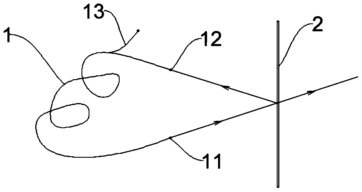
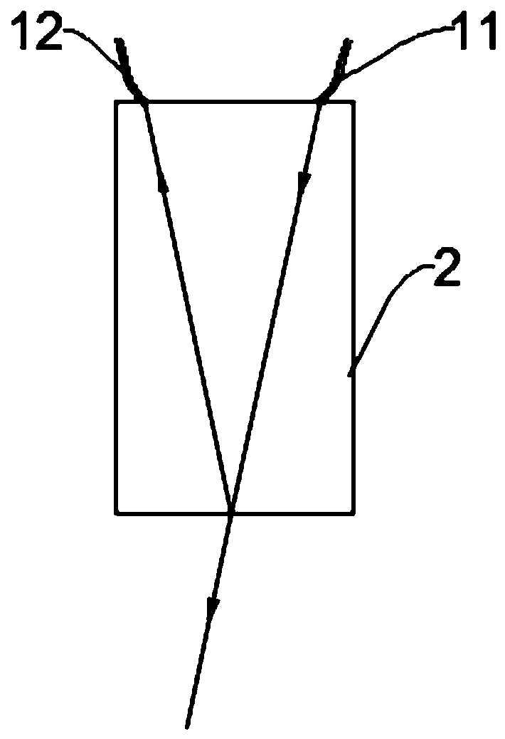
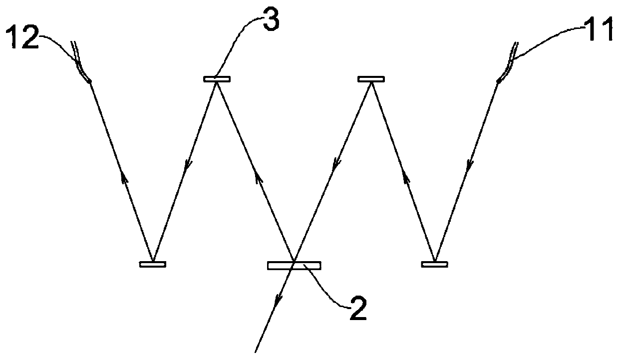
[0025] Such as figure 1 As shown, a laser collimation structure of the embodiment of the present invention includes an optical amplifier 1 and a beam splitter 2, wherein: the optical amplifier 1 has an output end 11 and an input end 12; Projected on the beam splitter 2; the light projected on the beam splitter 2 is at least partly reflected and transmitted as input light from the input end 12 of the optical amplifier 1 to re-enter the optical amplifier 1 and copied and amplified...


PUM


Abstract

The present invention relates to the technical field of laser application and in particular to a laser collimation structure and a product using the same. The laser collimation structure comprises anoptical amplifier and a beam splitter. The optical amplifier has an output end and an input end. The light output from the output end of the optical amplifier is transmitted and then is projected ontothe beam splitter. The light projected onto the beam splitter is at least partially reflected and transmitted, then, as input light, reenters the optical amplifier from the input end of the optical amplifier, and is copied and amplified. The light that is projected onto the beam splitter and is not reflected by the beam splitter is transmitted by the beam splitter to be collimated, and then is output and applied. By setting a condition of passing the light beam output by the optical amplifier through an external specific collimation and clustering path as an essential condition of laser resonance, laser collimation and clustering are achieved. The laser light generates an extremely small spot after irradiating an object and is linearly polarized light in a determined direction. A productusing the laser collimation structure is one of a laser cutting machine, a laser engraving machine, a laser scanner, and a nuclear fusion reaction ignition device.

Description

technical field [0001] The invention relates to the technical field of laser application, in particular to a laser collimation structure and products using the structure. Background technique [0002] A laser is a device capable of emitting laser light, which is widely used in industrial processing, laser medical treatment, military and other fields. The essential conditions for laser generation are population inversion and gain greater than loss, so the essential components in the device include two parts: excitation (or pumping) source and working medium with metastable energy level. Excitation is the excitation of the working medium to an excited state after absorbing external energy, creating conditions for the realization and maintenance of particle population inversion. The excitation methods include optical excitation, electrical excitation, chemical excitation and nuclear energy excitation. When the working medium has a metastable energy level, the stimulated radia...

Claims


Application Information

Patent Timeline
Patent Type & Authority Applications(China)
IPC IPC(8): H01S3/10H01S3/067G02B27/30G02B27/10
Inventor 李代甫
Owner 柳江
Why Eureka
Try Eureka