
A control method and system for a permanent magnet direct drive wind power system

A wind power system, permanent magnet direct drive technology, applied in wind power generation, single grid parallel feeding arrangement, etc., can solve the problems of complex structure of the controller, increase of converter volume and cost, energy fluctuation, etc., and achieve smooth energy change , reduce energy fluctuations, and achieve the effect of low-voltage ride-through

Active Publication Date: 2021-03-26
NORTH CHINA UNIVERSITY OF TECHNOLOGY
View PDF4 Cites 0 Cited by
  • Summary
  • Abstract
  • Description
  • Claims
  • Application Information

AI Technical Summary

Problems solved by technology

[0005] In the prior art, the maximum wind energy is tracked by controlling the converter on the machine side, and the grid-side converter controls the DC bus voltage to be stable. Therefore, the maximum wind power is fed into the grid in real time and the utilization rate of wind energy is improved. However, the wind speed Randomness leads to random output of wind turbines, so the energy fed into the grid by the wind power system fluctuates. In addition, the existing permanent magnet direct drive wind power generation system realizes low-voltage ride-through technical solutions mainly by installing an unloading circuit on the DC side , energy storage device to absorb excess energy, or parallel auxiliary converter to increase the output channel of DC side power
The control methods in the prior art all need to increase the external hardware circuit, which increases the volume and cost of the converter, resulting in a complex structure of the controller

Method used


Image

  • A control method and system for a permanent magnet direct drive wind power system
  • A control method and system for a permanent magnet direct drive wind power system
  • A control method and system for a permanent magnet direct drive wind power system

Examples


Embodiment Construction

[0050] The following will clearly and completely describe the technical solutions in the embodiments of the present invention with reference to the accompanying drawings in the embodiments of the present invention. Obviously, the described embodiments are only some, not all, embodiments of the present invention. Based on the embodiments of the present invention, all other embodiments obtained by persons of ordinary skill in the art without making creative efforts belong to the protection scope of the present invention.

[0051] The purpose of the present invention is to provide a control method and system of a permanent magnet direct drive wind power system capable of reducing energy fluctuations fed into the power grid by the wind power system and realizing low-voltage ride-through without adding hardware circuits.

[0052] In order to make the above objects, features and advantages of the present invention more comprehensible, the present invention will be further described i...


PUM


Abstract

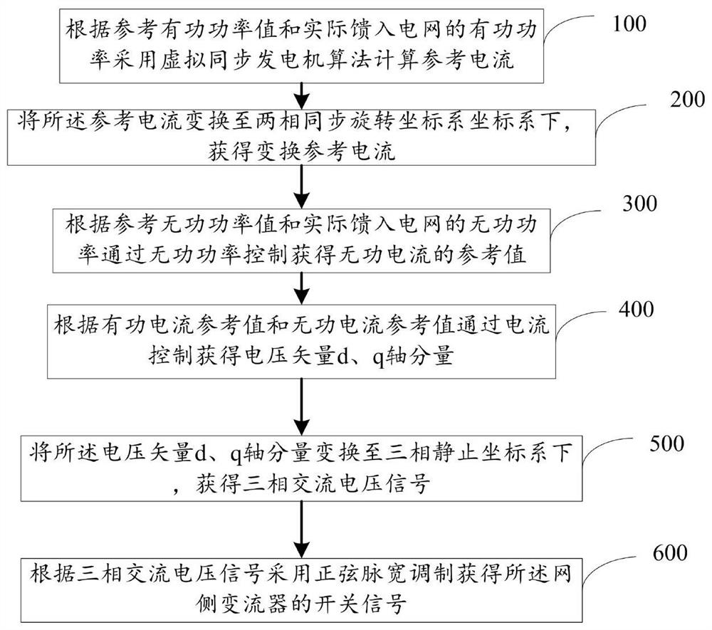
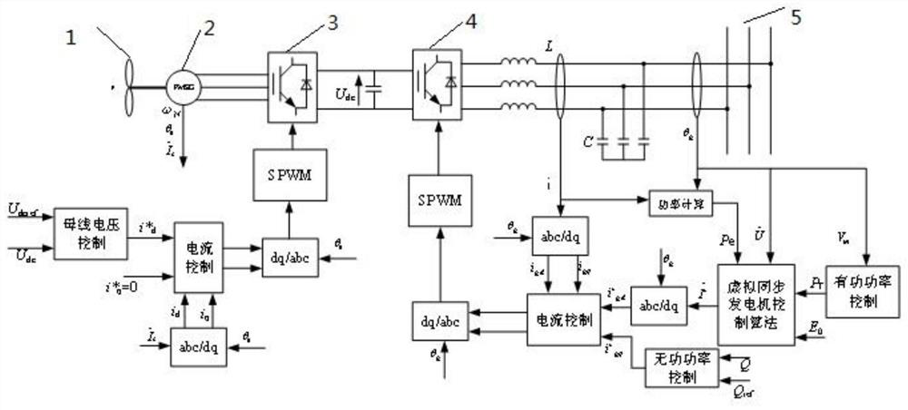
The invention discloses a control method and system for a permanent magnet direct drive wind power system. The control method is used for controlling the energy output of the permanent magnet direct drive wind power system, and comprises steps of: calculating a reference current by using a virtual synchronous generator algorithm according to a reference active power value and the active power actually fed into a power grid; transforming the reference current into a two-phase synchronous rotating coordinate system to obtain an active current component; obtaining a reference value of the reactive current; obtaining voltage vector d-axis and q-axis components by current control according to the active current reference value and the reactive current reference value; obtaining a three-phase ACvoltage signal; and obtaining a switching signal of a grid-side converter by using sinusoidal pulse width modulation according to the three-phase AC voltage signal. The active current component is calculated by using the virtual synchronous generator algorithm and then is transformed, thus, the current simulates the inertia of the synchronous generator and reduces the fluctuation of the energy fed into the power grid by the wind power system.

Description

technical field [0001] The invention relates to the field of wind power systems, in particular to a control method and system for a permanent magnet direct drive wind power system. Background technique [0002] With the development of global society and economy, people's demand for energy also increases. The energy issue has become an important basis for the sustainable economic development of various countries and an important strategic issue related to the development of the global economy. However, conventional hydrocarbons and derivatives of fossil energy (such as oil, natural gas, coal, etc.) have limited reserves, and a large amount of use will cause serious environmental pollution problems and threaten the ecological stability of the earth. Therefore, the direction of global energy development has shifted to clean and renewable energy. Among the existing renewable energy sources (such as solar energy, water energy, tidal energy, and wind energy), wind energy has the...

Claims


Application Information

Patent Timeline
Patent Type & Authority Patents(China)
IPC IPC(8): H02J3/38
CPCY02E10/76
Inventor 温春雪袁明华胡长斌朴政国周京华
Owner NORTH CHINA UNIVERSITY OF TECHNOLOGY
Learn More