
Virtual axis magnetic levitation flywheel energy storage device for electric vehicles

A technology for flywheel energy storage and electric vehicles, which is applied in the direction of electric vehicles, electromechanical devices, electric components, etc., can solve problems such as difficult large-scale popularization and application, increased weight and volume, and unsuitable vehicle environment, etc., to achieve suppression of gyro effect, energy Consumption and cost reduction, the effect of volume reduction

Active Publication Date: 2020-12-18
JIANGSU UNIV
View PDF4 Cites 0 Cited by
  • Summary
  • Abstract
  • Description
  • Claims
  • Application Information

AI Technical Summary

Problems solved by technology

Most flywheels are made of high-strength composite materials, so they are expensive and not easy to implement on a large scale
Although the flywheel made of metal materials has the advantage of low cost, its weight and volume will double on the basis of the same energy storage, which is not suitable for the vehicle environment

Method used


Image

  • Virtual axis magnetic levitation flywheel energy storage device for electric vehicles
  • Virtual axis magnetic levitation flywheel energy storage device for electric vehicles
  • Virtual axis magnetic levitation flywheel energy storage device for electric vehicles

Examples


Embodiment Construction

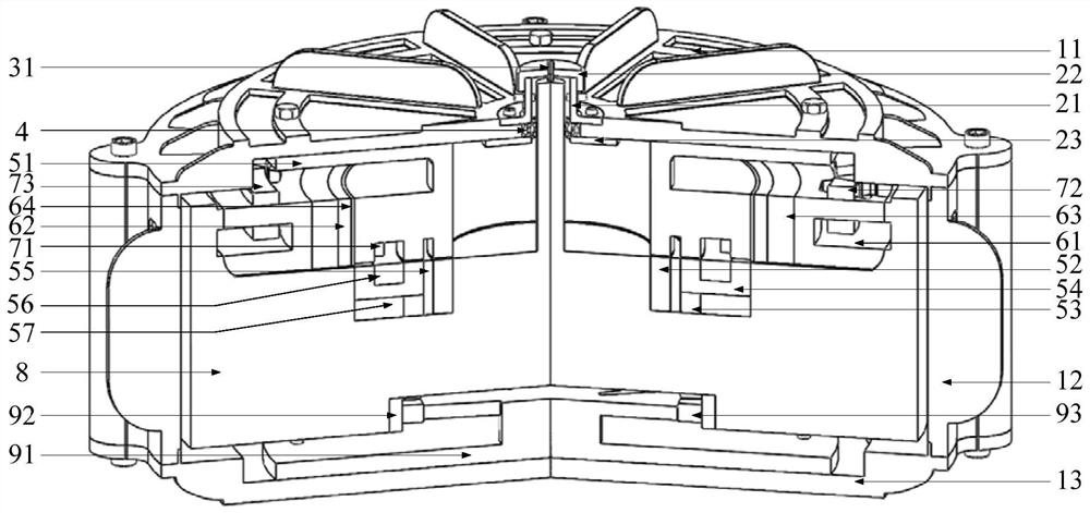
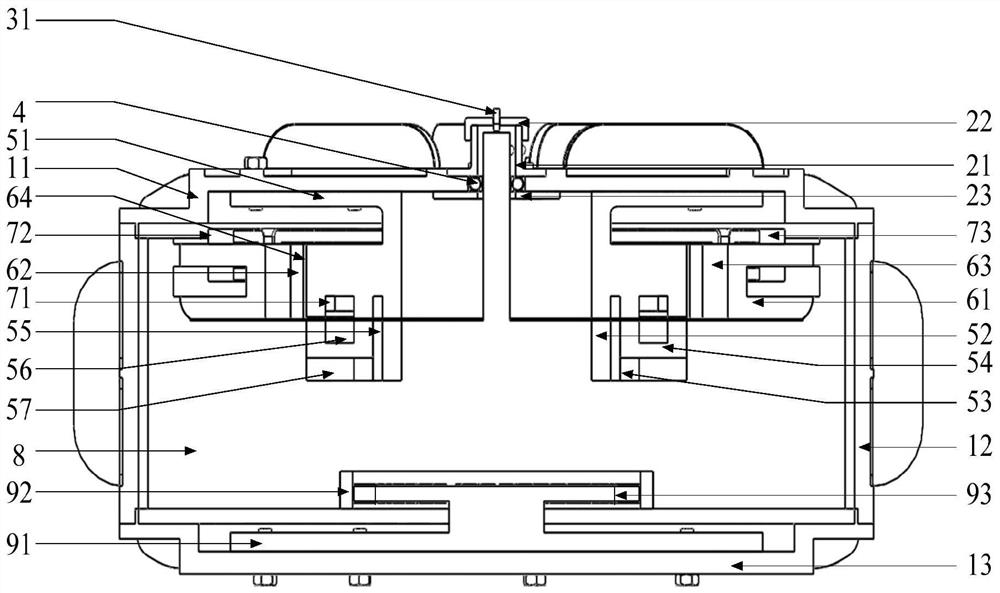
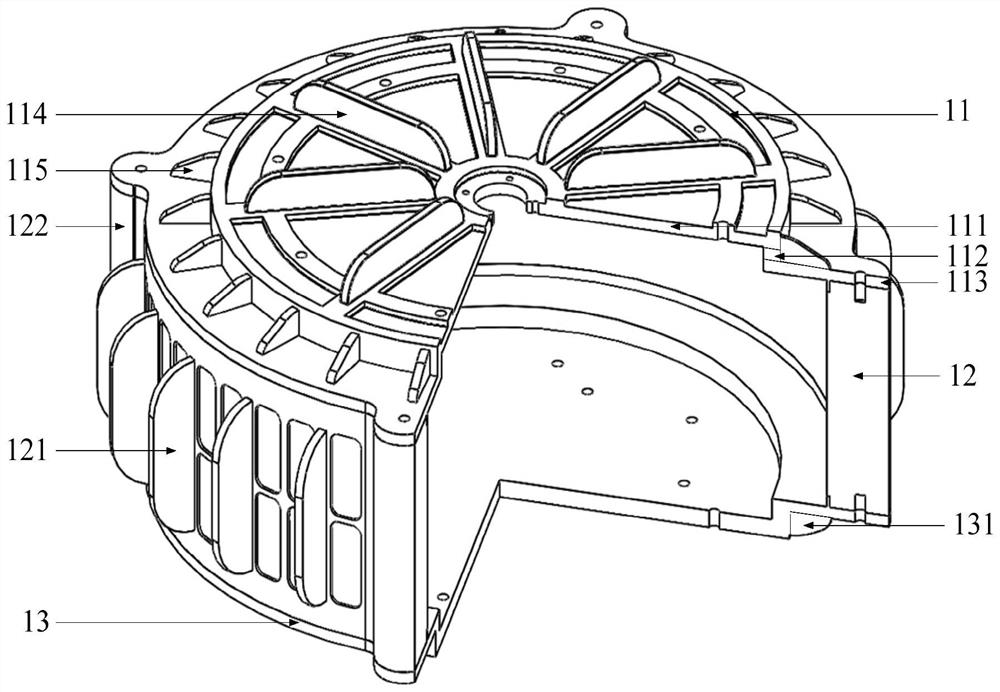
[0053] see figure 1 , figure 2 As shown, the outermost part of the present invention is a shell, and the shell is made up of a hollow cylindrical shell body 12, an upper end cover 11 and a lower end cover 13, the upper end of the shell body 12 is tightly and fixedly connected with the upper end cover 11, and the shell body 12 The lower end is tightly and fixedly connected with the lower end cover 13, and the shell cavity is surrounded by the shell body 12, the upper end cover 11 and the lower end cover 13.

[0054] A five-degree-of-freedom magnetic bearing, a flywheel rotor 8, and a multi-arc induction motor are coaxially distributed in the casing cavity. The five-degree-of-freedom magnetic bearing includes a stationary part and a rotating part. The stationary part includes axial stator 51, radial / torsion stator 61, radial permanent magnet 63 and other parts; the rotating part includes axial rotor 51 and axial inner ring permanent magnet 52. , the axial outer ring permanent...


PUM


Abstract

The invention discloses a virtual shaft type magnetic levitation flywheel energy storage device for an electric vehicle. The flywheel rotor has a lower annular body, a main cylinder, an upper annular body and a radial / The rotor yoke is twisted, the upper surface of the main cylinder is coaxially fixedly connected to the central cylinder, the middle of the upper surface of the central cylinder is coaxially fixedly connected to the long cylinder top, and the upper end of the long cylinder top passes through the five-degree-of-freedom magnet coaxially upwards. The static part of the bearing; the lower torus and the central cylinder are solid discs, and an annular groove is formed between the upper torus and the central cylinder, and a five-degree-of-freedom magnetic bearing is embedded concentrically in the annular groove The rotating part forms a cylindrical groove between the main cylinder and the lower annular body, and the motor conductor plate is embedded concentrically in the cylindrical groove; it can well suppress the gyro effect and achieve high stability performance, high integration and high bearing capacity.

Description

technical field [0001] The invention relates to a structure of a flywheel battery (also called a flywheel energy storage device), in particular to a vehicle-mounted magnetic levitation flywheel battery for an electric vehicle. Background technique [0002] As a mechanical energy storage battery, the flywheel energy storage device has the advantages of high charge and discharge efficiency, high specific power, no pollution and long life, and is an ideal auxiliary power battery for electric vehicles. At present, most flywheel energy storage devices have a topology with a long main axis of inertia. When the energy storage device is disturbed by the outside world, the gyroscopic effect is prone to occur, so it is not suitable for vehicle-mounted energy storage devices. Although the long-spindle flywheel energy storage device with a spherical surface can suppress the gyroscopic effect to a certain extent, instability still inevitably occurs due to the large axial length of the sp...

Claims


Application Information

Patent Timeline
Patent Type & Authority Patents(China)
IPC IPC(8): H02K7/02H02K7/09
CPCH02K7/025H02K7/09Y02E60/16Y02T10/64
Inventor 张维煜王健萍杨恒坤朱鹏飞程玲张林东朱熀秋
Owner JIANGSU UNIV
Learn More