Design method of kneecap prosthesis

A patella prosthesis and design method technology, applied in the direction of elbow joints, joint implants, knee joints, etc., to meet individual needs, facilitate recovery, and facilitate reconstruction

Active Publication Date: 2019-06-04
重庆熙科医疗科技有限公司
View PDF6 Cites 5 Cited by
  • Summary
  • Abstract
  • Description
  • Claims
  • Application Information

AI Technical Summary

Problems solved by technology

[0004] At present, there is no effective patella-femoral joint replacement prosthesis. The patellar prosthesis is designed to adapt to different anatomical characteristics and mechanical requirements. The innovative prosthesis technology is used to replace only the patella while ret

Method used


Image

  • Design method of kneecap prosthesis
  • Design method of kneecap prosthesis
  • Design method of kneecap prosthesis

Examples


Embodiment Construction

[0026] The present invention will be further described below in conjunction with the accompanying drawings and embodiments.

[0027] A kind of design method of patella prosthesis of the present invention, comprises the following steps:

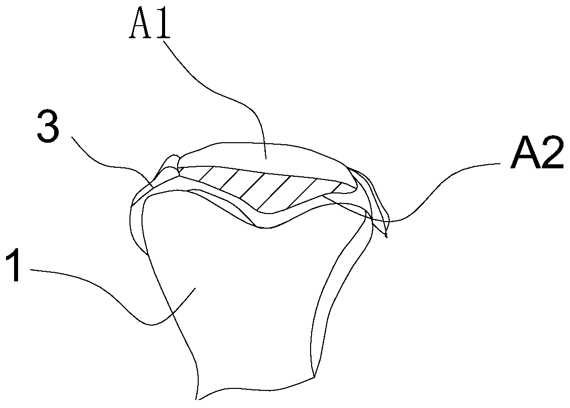
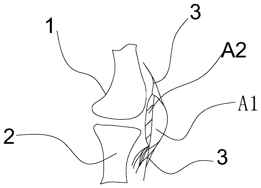
[0028] 1) Use CT or MRI to obtain high-precision three-dimensional raw data of the patient's knee joint, and use reverse engineering methods to establish a three-dimensional model of the patella;

[0029] 2) Establish the cutting plane of the three-dimensional model of the patella through the feature points of the patella, namely the upper pole, the lower pole, the connection point of the lateral retinaculum, and the connection point of the medial retinaculum;

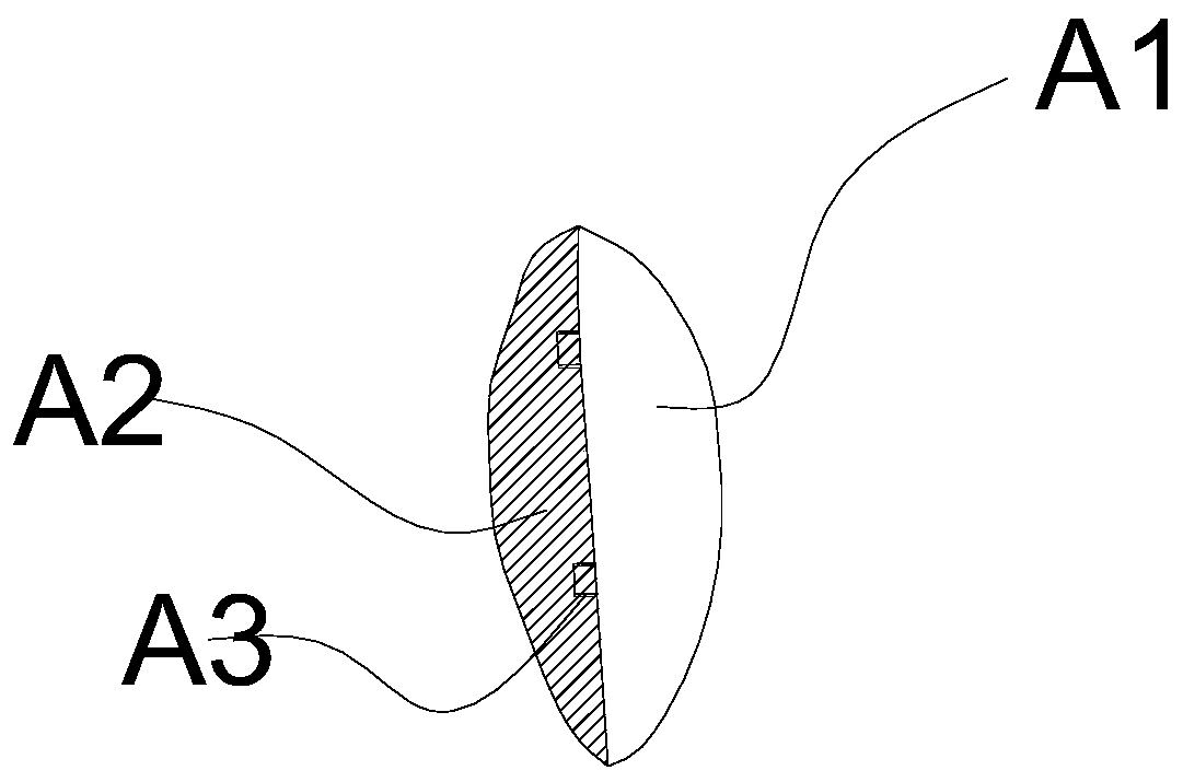
[0030] 3) Using the cutting surface to cut the three-dimensional model of the patella to obtain the three-dimensional model of the prosthesis and the patella retention zone;

[0031] 4) Based on the three-dimensional model, a protrusion is set on the cutting plane, and at the same tim...


PUM


Abstract

The invention discloses a design method of a prosthesis so as to meet motion functions and biological functions of kneecaps, and achieve the purpose of semi-kneecap prosthesis exchange. The design method of the prosthesis comprises the steps of obtaining high-precision three-dimensional raw data of the knee joint of a patient through CT or MRI, and constructing a kneecap three dimensional model bya reverse engineering method; and according to the feature points of the kneecaps, constructing the cutting plane of the kneecap three dimensional model, and by using the cutting plane, cutting the kneecap three dimensional model to obtain a three dimensional model A1 designed according to the prosthesis and a kneecap reserving band A2; and based on A1, designing a protrusion A3 on the cutting plane, and besides, based on A2, designing a groove A4 corresponding to the A3 in the position same as the cutting plane, to obtain a semi-kneecap prosthesis fixing structure. The semi kneecap prosthesis material is polyetheretherketone. A mold adopting a material increasing manufacturing method, a conventional manufacturing method or a combination of the material increasing manufacturing method andthe conventional manufacturing method is adopted for manufacturing the personalised kneecap prosthesis. Through an injection molding method, a high strength prosthesis structure and a high surface finish kneecap prosthesis articular facet are obtained.

Description

technical field [0001] The invention relates to the manufacture of a prosthesis, in particular to a design method of a patella prosthesis. Background technique [0002] It is well known that the knee joint is composed of the lower end of the femur, the upper end of the tibia, and the patella. It is the largest and most complex joint in the human body. Knee osteoarthritis is the most common musculoskeletal disease and the main cause of disability in middle-aged and elderly people. 85% Total knee replacement is due to knee osteoarthritis, knee replacements include: tibio-femoral arthroplasty and patella-femoral arthroplasty. Among them, tibial-femoral arthroplasty has been relatively mature technology, and the curative effect is relatively good. [0003] The patella is the largest sesamoid bone in the whole body. It is flat and millet-shaped. , down, left, and right movement is also the dynamic fulcrum of knee joint flexion and extension, which bears a lot of stress, usually...

Claims


Application Information

Patent Timeline
IPC IPC(8): A61F2/38A61F2/30
Inventor 范树迁黎静谢海琼王晗唐康来
Owner 重庆熙科医疗科技有限公司
Why Eureka
Try Eureka