Permanent magnetism aerogenerator and rotor thereof

A wind turbine and rotor technology, applied in wind power generation, magnetic circuit rotating parts, magnetic circuit shape/style/structure, etc., can solve the problems of bolt fatigue damage, high processing cost, high structural strength requirements, etc., and reduce assembly Difficult, large tangential force, reduced processing difficulty and the effect of processing accuracy requirements

Inactive Publication Date: 2019-06-04
ZHEJIANG UNIV +1
View PDF4 Cites 2 Cited by
  • Summary
  • Abstract
  • Description
  • Claims
  • Application Information

AI Technical Summary

Problems solved by technology

However, this fixing method has three disadvantages that are difficult to overcome: first, the positioning of the magnetic pole module is relatively difficult during installation; second, in order to overcome the huge tangential force received by the magnetic pole module when the generator is running, many bolts must be installed on the fixed parts In order to limit the possible circumferential movement of the magnetic pole module, there is also the risk of bolt fatigue damage; the other is that the stator and rotor must be assembled after the magnetic pole module is installed. The huge magnetic force generated by the permanent magnet greatly increases the difficulty of assembly. , this shortcoming is more obvious for large diameter rotors
However, the processing procedure of the "T"-shaped groove is cumbersome, requires high precision, and the processing cost is high; at the same time, the processing and packaging of the magnetic pole module matching the "T"-shaped groove is also difficult, and the structural strength requirements are also high.

Method used


Image

  • Permanent magnetism aerogenerator and rotor thereof
  • Permanent magnetism aerogenerator and rotor thereof
  • Permanent magnetism aerogenerator and rotor thereof

Examples


Embodiment 1

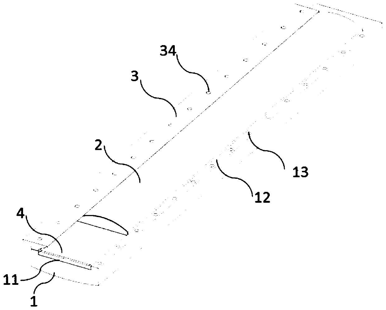
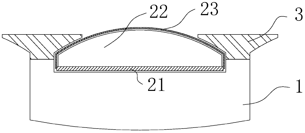
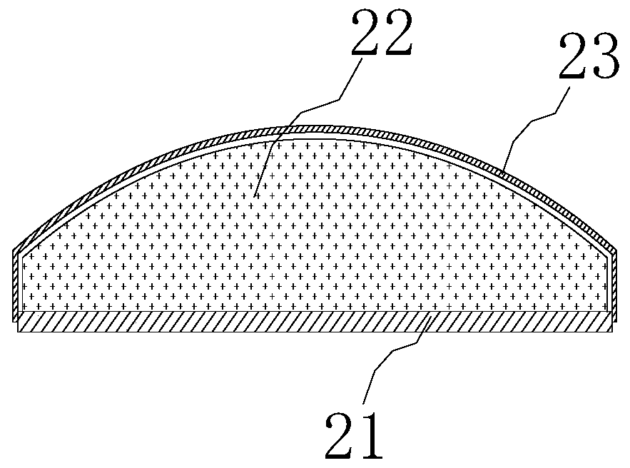
[0043] Such as figure 1 As shown, this embodiment provides a permanent magnet wind turbine rotor, which includes a rotor yoke 1 and a magnetic pole module 2. The rotor yoke 1 is provided with a plurality of circumferentially distributed grooves 11, and the grooves 11 The side wall is a protruding rib 12, and several radial threaded holes 13 are provided on the protruding rib 12; the shape of the bottom surface of the magnetic pole module 2 is adapted to the shape of the groove 11, and a part of the magnetic pole module 2 is embedded in the groove The inside of 11 is fixed with the fixing part 3, and one end of the fixing part 3 is connected with the locking part 4.

[0044] The rotor yoke 1 is a magnetically conductive material, and the radial cross-sectional shape of the groove 11 on the rotor yoke 1 is a rectangle. As an alternative, other shapes can also be used, such as a trapezoid. This shape is easy to process. The advantages. The groove 11 is formed by milling. The g...

Embodiment 2

[0050] Such as Figure 5 As shown, the basic structure of this embodiment is basically the same as that of Embodiment 1, the difference being that the fixing part 3 is a pressing block provided with a threaded hole 34 , and a plurality of pressing blocks are screwed to the protruding ribs 12 . With such a fixing part 3, the total mass of the rotor can be reduced. And a plurality of magnetic pole modules 2 are embedded in one groove 11 , which can reduce the magnetization difficulty of the packaged magnetic pole modules 2 .

Embodiment 3

[0052] Such as Figure 6 As shown, the basic structure of this embodiment is basically the same as that of Embodiment 2, the difference is that: the protruding ribs 12 are arranged at intervals in the length direction of the groove 11, and a threaded hole 13 is arranged between the two protruding ribs 12, and the pressure The block is threaded with the threaded hole 13 holes. In this way, it is beneficial to the positioning of the pressing block during installation.


PUM


Abstract

The invention discloses a permanent magnetism aerogenerator and a rotor thereof. A magnet yoke of a rotor includes grooves distributed along the circumferential direction, and the sidewall of each groove includes protruded ribs; the shape of the bottom side of a magnetic pole module matches that of the groove, and one part of the magnetic pole module is embedded into the groove; and a fixation part for compressing the magnetic pole module is arranged on the protruded ribs. The grooves are used to bear the magnetic pole module, the rotor and stator assembling difficulty and the installing and positioning difficulty of the magnetic pole assembly are reduced greatly, the fixation part is used to further fix the magnetic pole module, and the rotor processing difficulty and cost are reduced greatly.

Description

technical field [0001] The invention relates to the field of wind power generation, in particular to a permanent magnet wind generator rotor and a permanent magnet wind generator including the same. Background technique [0002] Wind power generation has been paid more and more attention by countries all over the world because of its environmental protection and pollution-free. The rotor of a permanent magnet synchronous wind turbine includes a rotor yoke and a permanent magnet. Generally, the permanent magnet is fixed to the rotor yoke by means of built-in or surface mount. The surface-mounted fixing has the advantages of relatively easy processing of the rotor yoke, relatively small amount of permanent magnets, relatively little flux leakage, and obvious gain effect after the permanent magnet shape is optimized. In order to avoid the corrosion and pollution of the permanent magnet due to environmental reasons, the permanent magnet is usually painted or encapsulated in the...

Claims


Application Information

Patent Timeline
Patent Type & Authority Applications(China)
IPC IPC(8): H02K1/27
CPCY02E10/72
Inventor 王海洋吴立建闻汇王斌王江乔方攸同
Owner ZHEJIANG UNIV
Why Eureka
Try Eureka