High-stability high-efficiency three-phase high-speed motor

A high-speed motor and high-efficiency technology, applied in the direction of electromechanical devices, electrical components, electric components, etc., can solve the problem that the three-phase permanent magnet brushless motor has obvious cogging torque, cannot obtain output power greater than three-phase motor, and cannot meet low Vibration, low noise and other issues, to achieve the effect of high utilization of effective magnetic flux, high utilization of structural space, and less magnetic flux leakage

Inactive Publication Date: 2019-06-04
武汉万至达智能科技有限公司 +1
View PDF10 Cites 2 Cited by
  • Summary
  • Abstract
  • Description
  • Claims
  • Application Information

AI Technical Summary

Problems solved by technology

[0004] Patents with application numbers 201611140022.3, 201611140021.9, and 201611141825.0 all disclose the technology of single-phase permanent magnet brushless motors. These single-phase permanent magnet brushless motors are simple in structure and easy to manufacture, but the inherent cogging torque causes obvious fluctuations in output torque , it is easy to cause obvious vibration and noise, and the inherent properties of single-phase motors make it impossible to obtain output power greater than that of three-phase motors
[0005] For the three-phase permanent magnet brushless motor with cogged structure, it is limited by the winding structure, and has no advantage in the demand for product miniaturization, especially under low voltage conditions, the winding slot fill rate is lower (the winding enameled wire is thicker) , and the cogging torque of the three-phase permanent magnet brushless motor is still obvious, which cannot meet the high requirements of low vibration and low noise

Method used


Image

  • High-stability high-efficiency three-phase high-speed motor
  • High-stability high-efficiency three-phase high-speed motor
  • High-stability high-efficiency three-phase high-speed motor

Examples


Embodiment Construction

[0027] In order to make the objectives, technical solutions and advantages of the present invention clearer, the present invention will be further described in detail below with reference to the accompanying drawings and embodiments. It should be understood that the specific embodiments described herein are only used to explain the present invention, but not to limit the present invention. In addition, the technical features involved in the various embodiments of the present invention described below can be combined with each other as long as they do not conflict with each other.

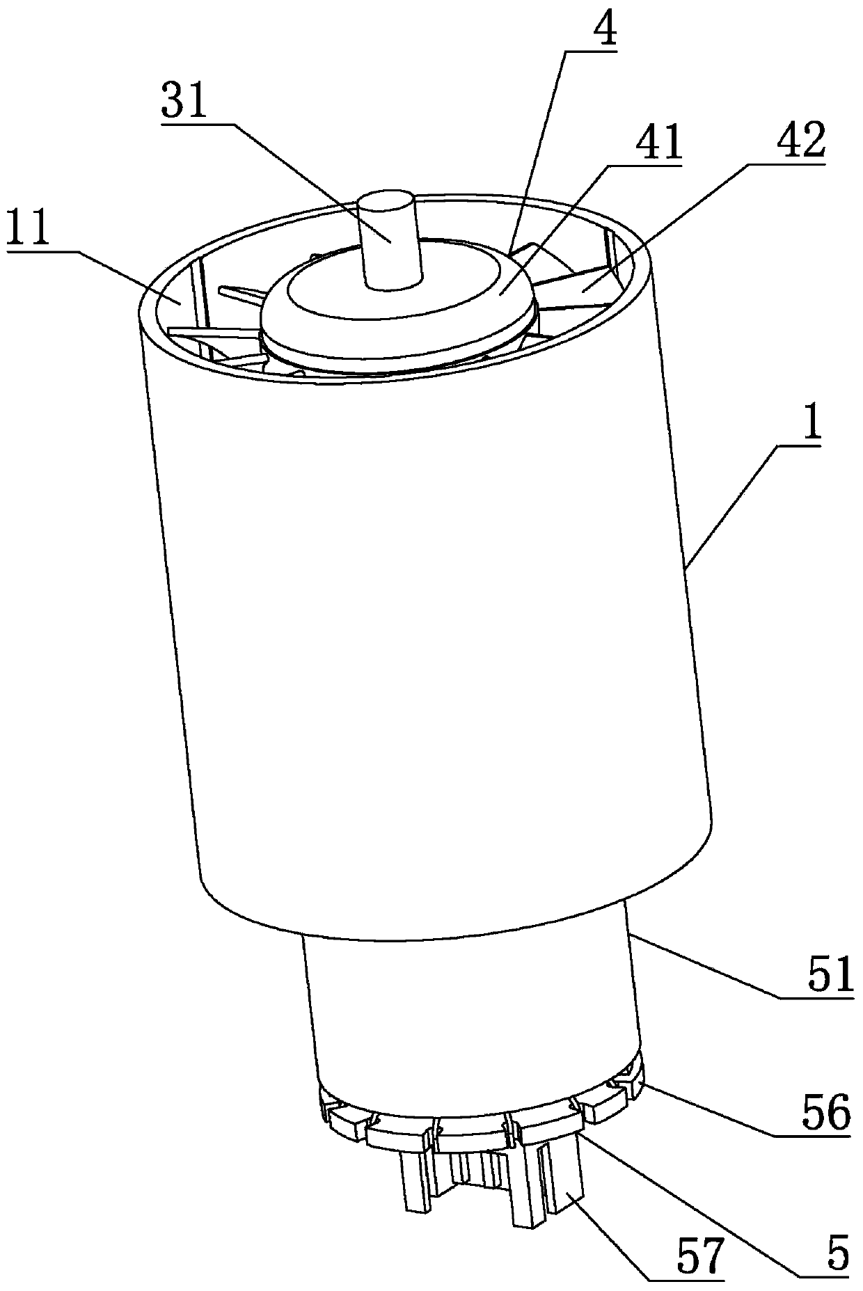
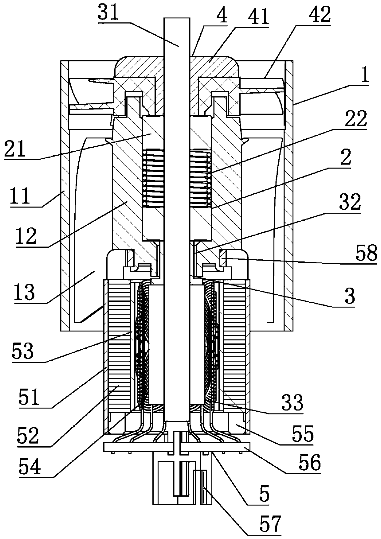
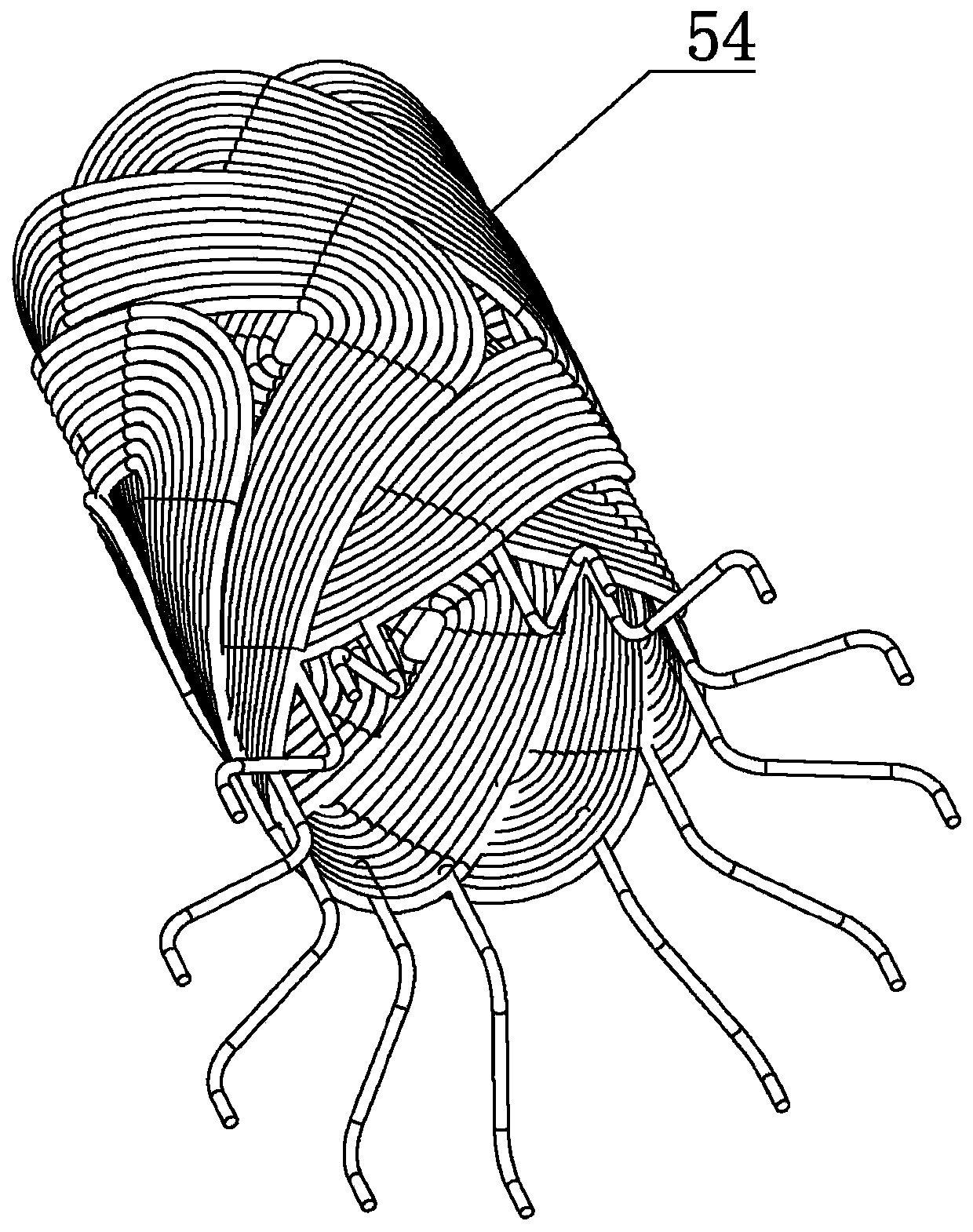
[0028] like Figure 1 to Figure 5 As shown, the present invention discloses a high-stable and high-efficiency three-phase high-speed motor, including a motor housing 1, a bearing assembly 2, a rotor assembly 3, an impeller assembly 4 and a stator assembly 5, wherein the motor housing 1 The axis of the motor is vertically arranged, and it includes a motor outer casing 11, an inner motor casing 12 an...


PUM


Abstract

The invention discloses a high-stability high-efficiency three-phase high-speed motor which comprises a motor casing, a rotor assembly, a bearing assembly, an impeller assembly and a stator assembly.The axis of the motor casing is arranged vertically; the rotor assembly comprises a rotating shafts and annular permanent magnets in the two poles; the impeller assembly is fixedly arranged in the upper end of the rotating shaft in a penetrating way; and the stator assembly comprises a stator casing, a stator, an insulating layer, a cup type winding, a backing plate, a PCB and a needle stand, thestator is fixedly mounted in the inner wall of the stator casing and is composed of silicon steel plates connected together, and the silicon steel plates are arranged coaxially and sequentially stacked from top to bottom. According to the motor, torque output is much more stable, the alternating frequency of the magnetic field is halved, and eddy current loss and hysteresis loss are lower; in themagnetic circuit structure, magnetic flux leakage is lower, the effective magnetic flux utilization rate is higher, and the motor output power and the output power are improved; and an air gap is uniform, and electromagnetic noise and vibration and useful power loss caused by higher harmonic waves are reduced.

Description

technical field [0001] The invention belongs to the technical field of high-speed permanent magnet motors, and more particularly, relates to a high-stable and high-efficiency three-phase high-speed motor. Background technique [0002] High-speed motors are widely used in household appliances, medical equipment, engraving, spraying and other fields. Compared with medium and low-speed power motor solutions, high-speed or ultra-high-speed motors can often subvert consumers' perception of traditional products. In most applications, the space size of the end product is getting higher and higher, which requires that the miniaturized high-speed motor can still obtain the expected output power. In addition, the high-speed motor with low vibration and low noise will make the product more favored by customers. [0003] At present, the power motors installed in household electrical products, such as hair dryers, air purifiers, and vacuum cleaners, usually use permanent magnet single-p...

Claims


Application Information

Patent Timeline
Patent Type & Authority Applications(China)
IPC IPC(8): H02K5/04H02K7/08H02K1/27H02K9/06H02K3/50H02K5/10
Inventor 张贝妮翁孟坤胡佳刘健
Owner 武汉万至达智能科技有限公司
Why Eureka
Try Eureka