Aortic stent windowing system
A fenestration system and aortic technology, applied in the field of medical devices, can solve the problems of complicated fenestration steps and excessive use of instruments, and achieve the effect of saving operation time and reducing operation risk
- Summary
- Abstract
- Description
- Claims
- Application Information
AI Technical Summary
Problems solved by technology
Method used
Image

Examples
Embodiment 1
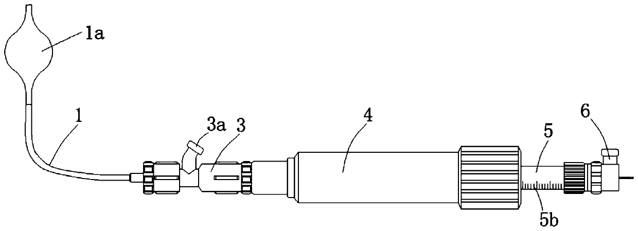
[0038] A fenestration system for aortic stents, aimed at solving the problems of complicated fenestration steps and a large amount of instruments used in the prior art, capable of synchronously expanding the window after fenestration through the reaming balloon set on the guide rod , to reduce operating steps and equipment usage, to save costs and reduce surgical risks, such as figure 1 , figure 2 , image 3 , Figure 4 , Figure 5 As shown, specifically set to the following structure:
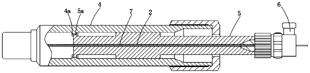
[0039]As the basic setting of the aortic stent fenestration system, the aortic stent fenestration system includes a flexible catheter 1, a flexible guide rod 2 and a guide rod filling joint 6. The catheter 1 and guide rod 2 can follow the trend of human blood vessels and the inner diameter of the vessel. There is a guide rod cavity through the catheter 1, the guide rod 2 can freely pass through or penetrate into the guide rod cavity of the catheter 1, and the guide rod 2 is inserted into...
Embodiment 2
[0049] This embodiment is further optimized on the basis of the above-mentioned embodiments, further to better realize the present invention, especially adopt the following configuration structure:
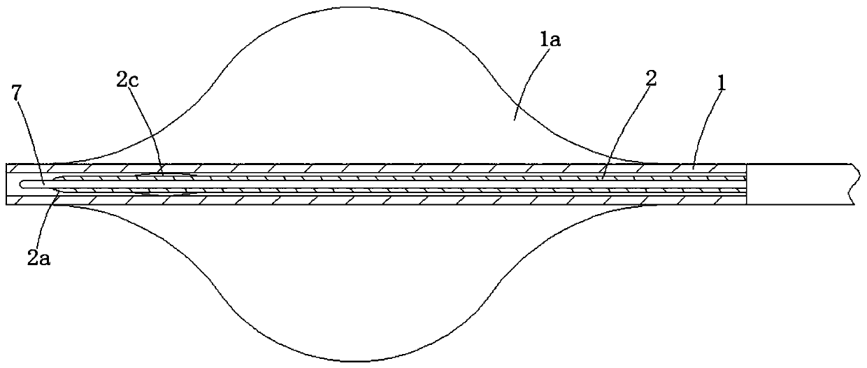
[0050] A helical cutting edge 2 b for cutting the film is provided at the front end of the guide rod 2 , and the helical cutting edge 2 b extends helically along the axial direction of the guide rod 2 . Moreover, the helical cutting edge 2b needs to be located between the puncture needle 2a and the reaming balloon 2c, and the diameter of the helical cutting edge 2b is larger than the diameter of the puncture needle 2a and smaller than the inflated outer diameter of the reaming balloon 2c. A helical cutting edge 2b is provided at the rear end of the puncture needle 2a to further perform window opening, reaming and through-hole operations on the window position of the coating after the puncture needle 2a has opened the window, and can form a better and larger The window is then ream...
Embodiment 3
[0053] This embodiment is further optimized on the basis of the above-mentioned embodiments, further to better realize the present invention, especially adopt the following configuration structure:
[0054] The puncture needle 2a is a tapered needle to facilitate puncturing the membrane of the stent graft. In addition, a side hole 2d communicating with the guide wire lumen is opened at the inclined surface of the puncture needle 2a, and the side hole 2d is used to assist radiography. After opening the window and reaming the hole, pull out the guide wire 7 from the guide rod 2, inject contrast agent into the guide wire cavity of the refrigerator guide rod 2, and the contrast agent will be discharged from the side hole 2d and adhere to the window opening.
PUM
 Abstract
Description
Claims
Application Information
 - Generate Ideas
- Intellectual Property
- Life Sciences
- Materials
- Tech Scout
- Unparalleled Data Quality
- Higher Quality Content
- 60% Fewer Hallucinations
Browse by: Latest US Patents, China's latest patents, Technical Efficacy Thesaurus, Application Domain, Technology Topic, Popular Technical Reports.
© 2025 PatSnap. All rights reserved.Legal|Privacy policy|Modern Slavery Act Transparency Statement|Sitemap|About US| Contact US: help@patsnap.com