
An active front wheel steering control method for electric vehicles with automatically adjustable control parameters
An active front wheel steering and automatic adjustment technology, which is applied to steering mechanisms, vehicle components, transportation and packaging, etc., can solve the problems of direct yaw moment control that is difficult to achieve control effects, controller discontinuity, system crashes, etc., to achieve Effects of reducing traffic accidents, reducing buffeting problems, and reducing costs
- Summary
- Abstract
- Description
- Claims
- Application Information
AI Technical Summary
Problems solved by technology
Method used
Image

Examples
Embodiment Construction
[0061] The invention provides an active front wheel steering control strategy of an electric vehicle whose control parameters can be automatically adjusted. In order to make the object, technical solution and effect of the present invention more clear and definite, the present invention will be further described in detail below with reference to the accompanying drawings and examples. It should be understood that the specific embodiments described here are only used to explain the present invention, not to limit the present invention.
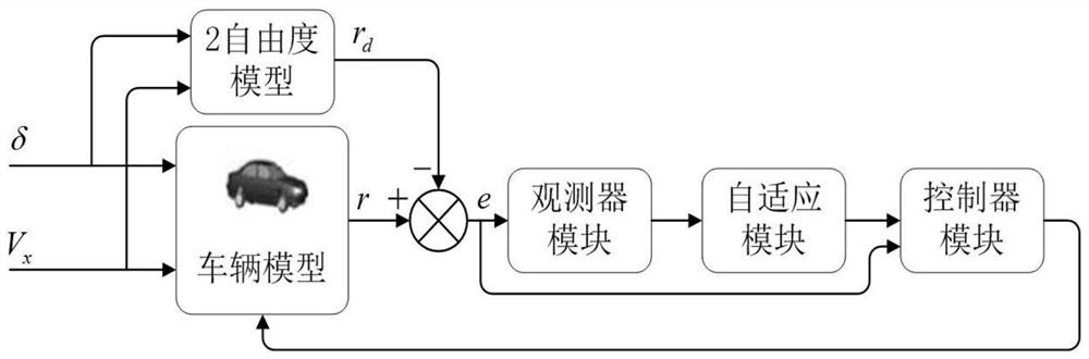
[0062] figure 1 Shown is a schematic diagram of the system relationship of the present invention, which includes 1. a linear two-degree-of-freedom vehicle model, 2. Carsim software (whole vehicle model), 3. an observer module, 4. an adaptive module, and 5. a discontinuous control module.
[0063] Based on the above-mentioned system, explain the present invention to the vehicle stability control method under complex working conditions by concre...
PUM
 Abstract
Description
Claims
Application Information