Cotton cloth cutting equipment for textile production
What is Al technical title?
Al technical title is built by PatSnap Al team. It summarizes the technical point description of the patent document.
A cotton cloth and equipment technology, applied in the field of cotton cloth cutting equipment, can solve the problems of cloth deviation, cloth error, health hazards of workers, etc., and achieve the effect of improving quality and increasing safety
Inactive Publication Date: 2019-06-07
泉州朔康工业设计服务有限公司
View PDF15 Cites 5 Cited by
Summary
Abstract
Description
Claims
Application Information
AI Technical Summary
This helps you quickly interpret patents by identifying the three key elements:
Problems solved by technology
Method used
Benefits of technology
Problems solved by technology
[0006] 1. The existing cotton cloth cutting equipment manually pulls the cloth under the laser for cutting. This method is very inconvenient and the work efficiency is not high, and manual pulling may easily cause the cloth to shift The situation makes the cut fabric prone to errors, resulting in waste of fabric
[0007] 2. The existing cotton cloth cutting equipment is manually fixed the cloth during the cutting work, the stability is not high, and it is not convenient for laser cutting
[0008] 3. The existing cotton cloth cutting equipment is not safe because the cutting work is carried out by laser, and the staff is prone to safety accidents if they do not pay attention
[0009] 4. With the existing cotton cloth cutting equipment, after the laser touches the cloth, the toxic gas after burning will appear at the cutting place of the cloth. If a large amount is discharged into the air, it will cause harm to the health of the staff
Method used
Image
Click on the blue label to locate the original text in one second.
Reading with bidirectional positioning of images and text.
Examples
Embodiment Construction
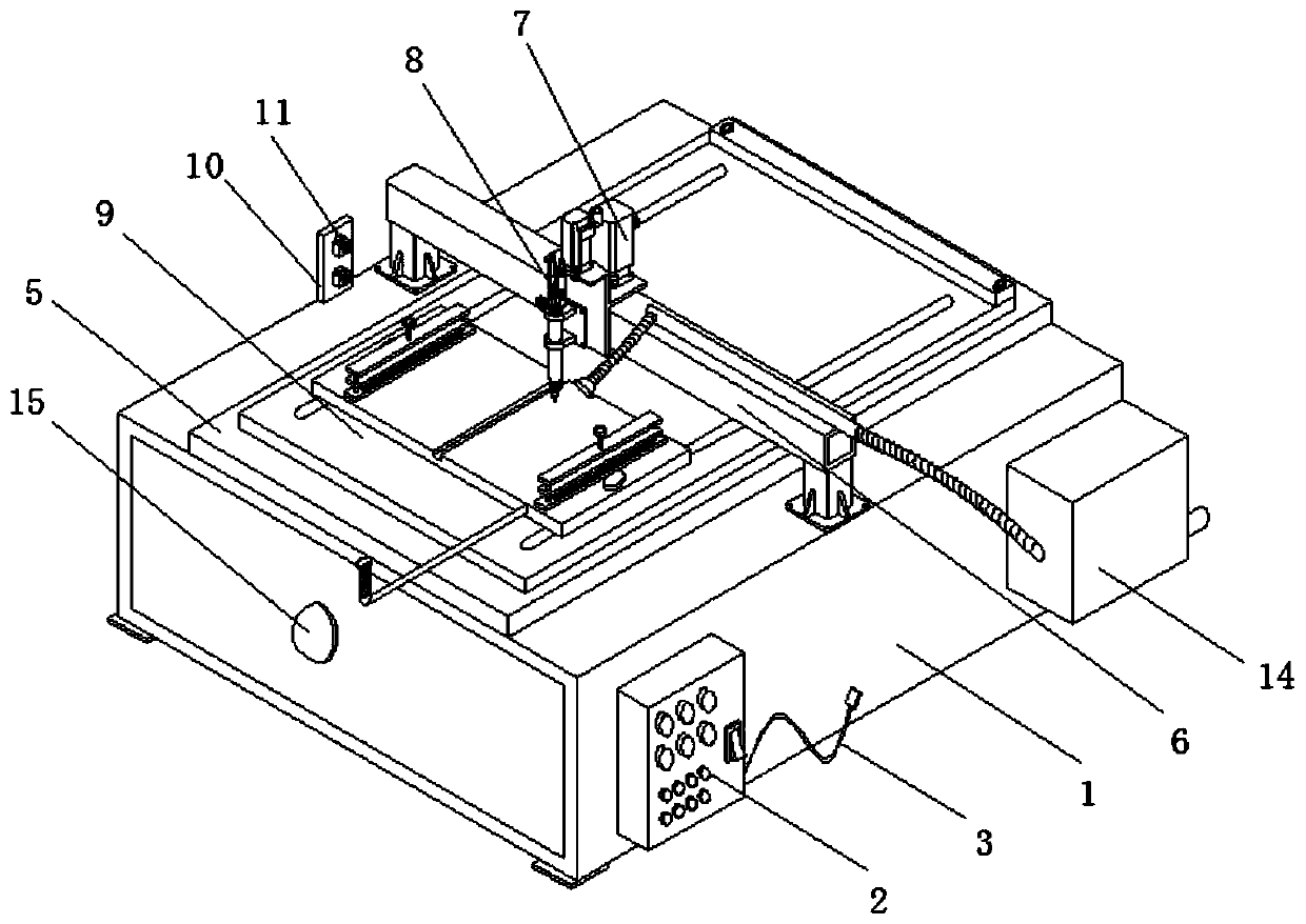
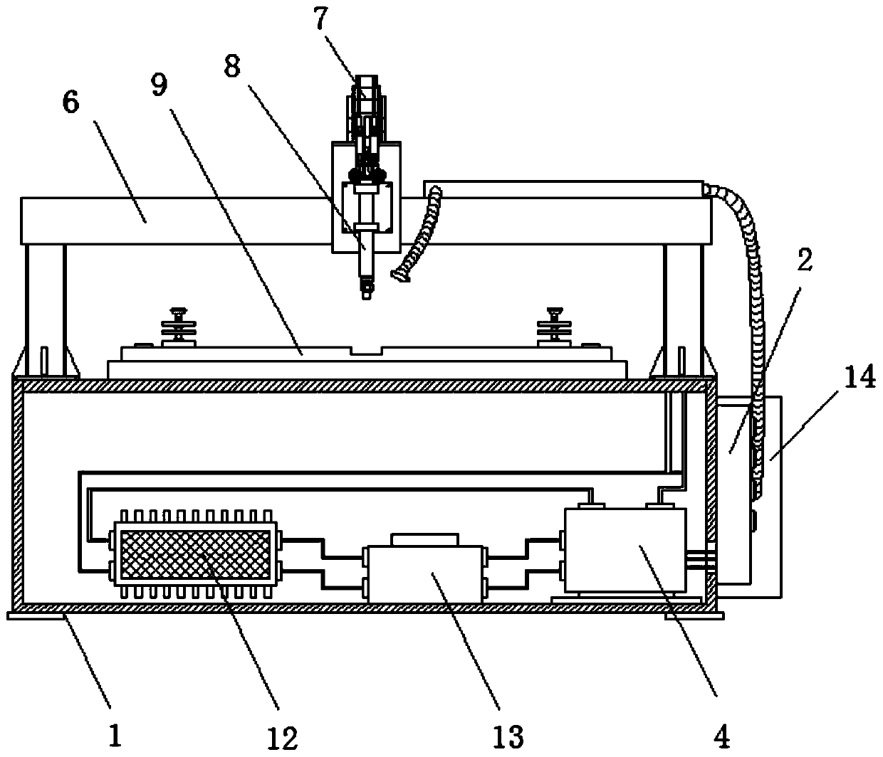
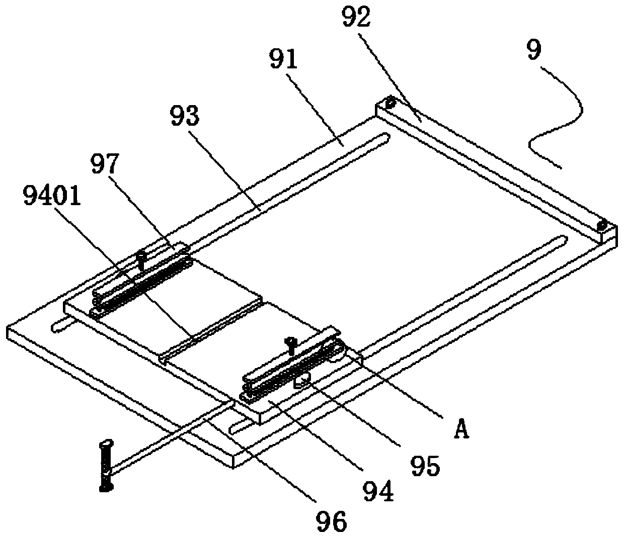
[0050] The following will be combined with Figure 1-7 The present invention is described in detail, and the technical solutions in the embodiments of the present invention are clearly and completely described. Apparently, the described embodiments are only some of the embodiments of the present invention, not all of them. Based on the embodiments of the present invention, all other embodiments obtained by persons of ordinary skill in the art without making creative efforts belong to the protection scope of the present invention.
[0051] The present invention provides a cotton cloth cutting equipment for textile production through improvement, including a chassis 1, a control box 2, a power cord 3, a storage battery 4, a workbench 5, a beam 6, a laser emitter 7, a laser tube 8, and a pushing device 9. Bracket 10, infrared sensor 11, single-chip microcomputer 12, circuit breaker 13, exhaust device 14 and alarm 15, the control box 2 is welded on the right front side of the chas...
PUM
Abstract
The invention discloses cotton cloth cutting equipment for textile production. The cotton cloth cutting equipment comprises a machine box, a control box, a power line, a storage battery, a working table, a cross beam, a laser emitter, a laser tube, a pushing device, a support, an infrared sensor, a single chip microcomputer, a circuit breaker, an exhaust device and an alarm, wherein the control box is welded to the front side of the right end of the machine box, the power line is inserted in the rear end of the control box, the storage battery is arranged at the right end of the interior of the machine box, the working table is welded to the middle of the top end of the machine box, and the bottom of the left end and the bottom of the right end of the cross beam are fixed on the left sideand the right side of the middle part of the top end of the machine box through screws on the periphery of the support frame. According to the cotton cloth cutting equipment, a pushing device is arranged on the working table, after cotton cloth is fixed, a push rod is pushed to enable a sliding plate to slide on a bottom plate, a sliding rod slides in a sliding groove so that the sliding plate canbe kept sliding along a straight line, then the cotton cloth can be linearly cut when passing through laser, the cutting work of workers is facilitated, meanwhile, the deviation is avoided, and the quality of the cotton cloth after being cut is improved.
Description
technical field [0001] The invention relates to the field of cutting equipment, in particular to a cotton cloth cutting equipment for textile production. Background technique [0002] Spinning and weaving The general term for spinning and weaving. Ancient Chinese textile and printing and dyeing technology has a very long history. As early as in the primitive society, in order to adapt to climate change, the ancients knew how to use local materials and use natural resources as textile materials. and printing and dyeing raw materials, as well as the manufacture of simple textile tools. Until today, our daily clothes, some daily necessities and artworks are the products of textile and printing and dyeing technology. Cloth is a kind of textile. When using cloth to make products, It is necessary to cut the fabric, and the quality of cutting is very important. However, the existing cutting equipment is generally cut by laser, which can be cut efficiently. The corner improves the ...
Claims
Application Information
Patent Timeline
Application Date:The date an application was filed.
Publication Date:The date a patent or application was officially published.
First Publication Date:The earliest publication date of a patent with the same application number.
Issue Date:Publication date of the patent grant document.
PCT Entry Date:The Entry date of PCT National Phase.
Estimated Expiry Date:The statutory expiry date of a patent right according to the Patent Law, and it is the longest term of protection that the patent right can achieve without the termination of the patent right due to other reasons(Term extension factor has been taken into account ).
Invalid Date:Actual expiry date is based on effective date or publication date of legal transaction data of invalid patent.