Crankshaft ventilation system, turbocharged engine and automobile

A technology for turbocharging and ventilation systems, applied in crankcase ventilation, engine components, machines/engines, etc., can solve the problems of high cost, many connecting pipes, and large space occupied by the crankshaft ventilation system. The effect of reducing the number of connecting pipes and reducing the high cost problem

Active Publication Date: 2020-09-08
ZHEJIANG GEELY HLDG GRP CO LTD +1
View PDF6 Cites 0 Cited by
  • Summary
  • Abstract
  • Description
  • Claims
  • Application Information

AI Technical Summary

Problems solved by technology

However, the cost of this solution is relatively high, the two crankshaft ventilation systems take up a lot of space, and there are many connecting pipelines, which is not conducive to the development and use of small turbocharged engines

Method used


Image

  • Crankshaft ventilation system, turbocharged engine and automobile
  • Crankshaft ventilation system, turbocharged engine and automobile
  • Crankshaft ventilation system, turbocharged engine and automobile

Examples


Embodiment 1

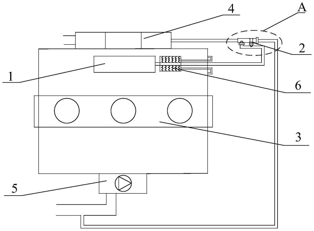
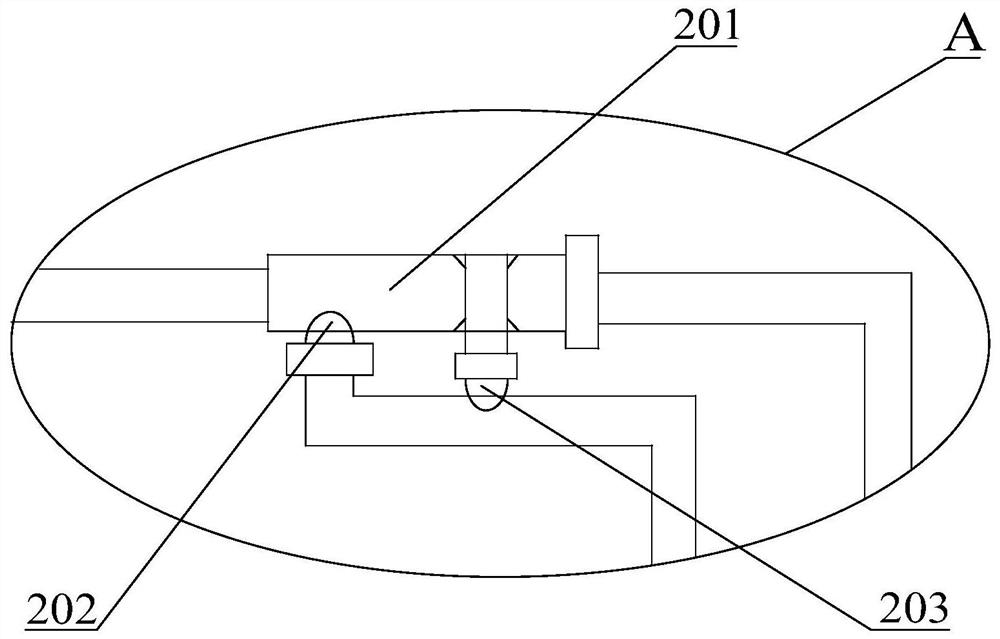
[0045] Such as figure 1 , figure 2 as shown, figure 1 It shows a schematic structural diagram of the first crankshaft ventilation system provided by the embodiment of the present application; figure 2 for figure 1 Schematic diagram of the enlarged structure at A.

[0046] The first crankshaft ventilation system is applied to the turbocharged engine 3, including the oil-air separator 1, and also includes the direction control assembly 2, and the direction control assembly 2 is respectively connected with the intake manifold 4, the intake manifold 4 and the turbocharged engine 3 through pipelines. The turbocharger 5 of the turbocharged engine 3 communicates with the oil-air separator 1; wherein, the direction control assembly 2 controls the gas separated from the oil-air separator 1 to flow to the intake manifold 4 according to the working state of the turbocharger 5 Or turbocharger 5.

[0047] From this analysis, it can be known that in the crankshaft ventilation system ...

Embodiment 2

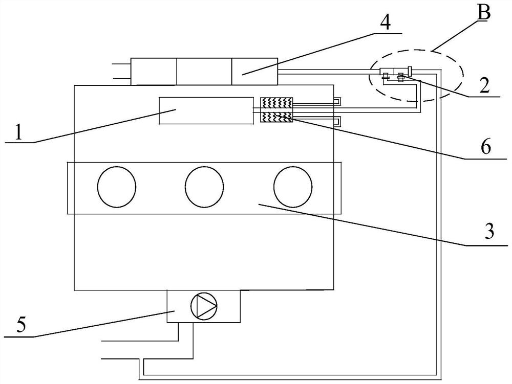
[0061] Such as image 3 , Figure 4 as shown, image 3 A schematic structural diagram of the second crankshaft ventilation system provided in the embodiment of the present application; Figure 4 for image 3 Schematic diagram of the enlarged structure at B.

[0062] The second crankshaft ventilation system is applied to the turbocharged engine 3, including the oil-air separator 1, and also includes the direction control assembly 2, and the direction control assembly 2 is respectively connected with the intake manifold 4, the intake manifold 4, and the turbocharged engine 3 through pipelines The turbocharger 5 of the turbocharged engine 3 communicates with the oil-gas separator 1;

[0063] Wherein, the direction control assembly 2 controls the gas separated from the oil-gas separator 1 to flow to the intake manifold 4 or the turbocharger 5 according to the working state of the turbocharger 5;

[0064] Specifically, the direction control assembly 2 includes a first connecti...

Embodiment 3

[0074] Such as Figure 5 , Image 6 as shown, Figure 5 A partial structural schematic diagram of a turbocharged engine provided in an embodiment of the present application; Image 6 for Figure 5 Schematic diagram of the enlarged structure at C.

[0075] A turbocharged engine 3 includes a first crankshaft ventilation system.

[0076] In addition, the turbocharged engine 3 may also include a second crankshaft ventilation system, but since the first crankshaft ventilation system and the second crankshaft ventilation system have the same functional effect, the embodiment of the present application only uses the first crankshaft ventilation system. Take the turbocharged engine 3 of the crankshaft ventilation system as an example.

[0077] Preferably, an intercooler 7 is provided between the intake manifold 4 and the turbocharger 5 , and the intercooler 7 is used to cool down the gas pressurized by the turbocharger 5 .

[0078]In the embodiment of the present application, wh...


PUM


Abstract

The invention provides a crankshaft ventilation system, a turbo-supercharged engine and a vehicle, and relates to the technical field of turbo-supercharged engines. The crankshaft ventilation system is applied to the turbo-supercharged engine, comprises an oil-gas separator, and further comprises a direction control assembly, wherein the direction control assembly communicates with an intake manifold of the turbo-supercharged engine, a turbocharger of the turbo-supercharged engine, and the oil-gas separator through pipelines; the direction control assembly controls gas separated out from the oil-gas separator to flow into the intake manifold or turbocharger according to the operating state of the turbocharger. Due to the addition of the direction control assembly, the crankshaft ventilation system is used for replacing the existing double crankshaft ventilation system, so that the problem of ventilation of a crankcase of theturbo-supercharged engine can be solved, the high cost problembrought about by the double crankshaft ventilation system can be effectively reduced, the space occupied by one crankshaft ventilation system is small, the connecting pipeline is small, and the development and use of the small turbo-supercharged engine are facilitated.

Description

technical field [0001] The invention relates to the technical field of turbocharged engines, in particular to a crankshaft ventilation system, a turbocharged engine and an automobile. Background technique [0002] The turbocharged engine crankcase ventilation system is used to separate turbocharged engine crankcase blow-by gases. However, in extreme climates, the crankcase ventilation system of turbocharged engines is prone to blockage due to icing and other reasons; The phenomenon of air leakage and oil leakage; in severe cases, the plugging of the turbocharged engine will pop out due to the excessive internal pressure of the turbocharged engine, endangering the operation safety of the turbocharged engine. [0003] In the existing technical solutions to solve the crankcase ventilation problem of turbocharged engines, two crankshaft ventilation systems are generally designed to separate the oil-air mixture entering the intake manifold and the turbocharger, and then separate...

Claims


Application Information

Patent Timeline
Patent Type & Authority Patents(China)
IPC IPC(8): F01M13/00F01M13/04
Inventor 徐鹏
Owner ZHEJIANG GEELY HLDG GRP CO LTD
Why Eureka
Try Eureka