Long-row lamp and assembling method thereof

An assembly method and long-row technology, applied in the direction of slender light sources, lighting devices, air-proof/water-proof devices, etc., can solve the problems of cumbersome parts production processes, high manual production costs, high logistics and storage costs, and increase the heat dissipation effect , performance and cost optimization, simple structure effect

Inactive Publication Date: 2019-06-07
慈溪市万诚纺织品有限公司
View PDF0 Cites 0 Cited by
  • Summary
  • Abstract
  • Description
  • Claims
  • Application Information

AI Technical Summary

Problems solved by technology

Its principle structure is limited, and the product strength is poor. The application method is mainly used in a stable and static environment, such as a computer CPU radiator
The strength of the product is poor, and the market application environment is limited; 2. Because the existing technology mainly conducts heat through heat pipes, the diameter of the pipe, the performance of the cooling medium, and the size of the heat sink directly affect the heat dissipation of the product, so the size is often 3. In terms of production technology, the Mohs hardness of aluminum is about 2.75, and its heat sink is very thin, and it is easy to be bumped and deformed during the assembly process, resulting in a greatly reduced product yield and high labor production costs; its products The parts are basically aluminum heat sinks, copper tubes, cooling medium, fixing parts, etc. The heat pipe components mainly include four parts: tube shell, end cover, liquid-absorbing core, and waist plate
The production process of parts is cumbersome and the cost of materials is high (including inconvenient installation)
There are many types of parts, and the refrigeration medium also requires certain requirements for storage, so the cost of logistics and storage is high

Method used


Image

  • Long-row lamp and assembling method thereof
  • Long-row lamp and assembling method thereof

Examples


Embodiment 1

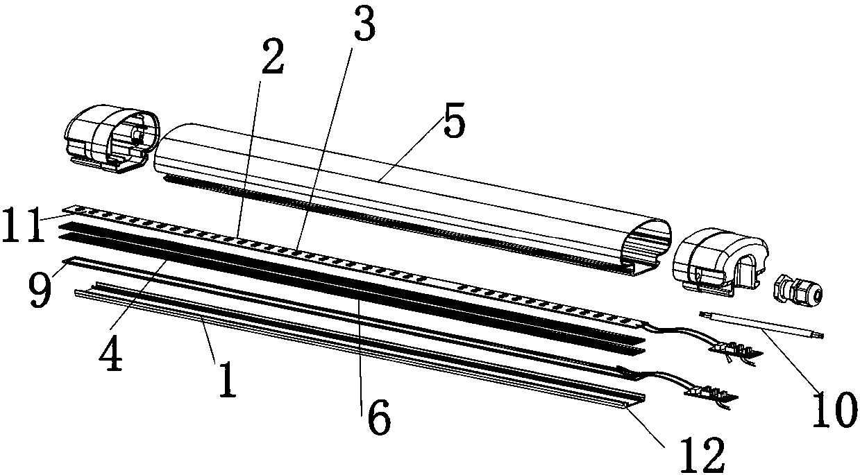
[0022] like Figure 1-Figure 2 The shown embodiment provides a long row of lights, including a mounting base 1, a housing 2 connected to the mounting base 1, and an LED lamp assembly 3 located in the housing 2. Heat sink 4, several heat sinks 4 are spliced ​​together, and the heat sink 4 includes a body 5, which is provided on the end surface of the body 5, and the heat sink 4 is in the shape of a block. The block shape is arranged on the top of the heat sink 4 in a honeycomb structure, and a sealing ring 9 is provided between the installation base 1 and the circuit board 2. The installation base 1 is a heat-conducting metal base, and the metal base is an aluminum base. Gold base or copper base.

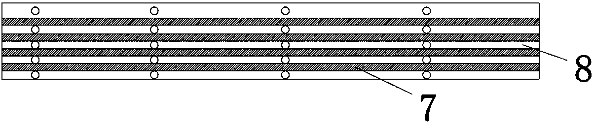
[0023] The long row of lamps provided in this embodiment conducts heat through the heat dissipation bar 7 between the heat sink 6 and the heat sink 6. The design of the heat dissipation bar 7 not only ensures the circulation of the air, but also ensures the heat dissipation area. T...


PUM


Abstract

The invention discloses a long-row lamp, which comprises a mounting base, a circuit board, LED lamp beads, a radiating assembly, a mask and a silicon film, wherein the LED lamp beads are arranged on the circuit board; the circuit board is arranged at the upper end of the mounting base through the silicon film; the mask is covered and connected with the upper end of the mounting base; the radiatingassembly is arranged at the lower end of the mounting base; the radiating assembly is formed by splicing a plurality of radiating fins;the long-row lamp transmits heat through radiating strips between the radiating fins; the design of the radiating strips not only ensures the circulation of air, but also ensures the radiating area, so that the product achieves the best heat conduction and radiation effect; according to the radiation requirement of the product, the product can be fixedly connected through the overlapping combination of the radiating fins and screws, so that the structure is simple, the installation is convenient, and the damaged radiating fins are replaced conveniently.

Description

technical field [0001] The invention relates to a lamp, in particular to a row lamp. Background technique [0002] Long row lights are a kind of decorative and warning lamps that have only recently appeared in the world. The long row of lights has many uses: it can be used as a warning light for special vehicles; installed on the top or edge of a tall building, it can make the building look magnificent at night; installed on billboards to attract attention, installed on roadblocks The flashes are particularly eye-catching and safer. The LED row lamp light-emitting module is much superior to the bulb light source and flash light source commonly used in the past. It has a long life (50,000 hours), a wide viewing angle, anti-vibration, easy circuit control, less heat generation, energy saving, and It has the characteristics of dynamic, convenient installation and safe use. [0003] But the existing long row lamp has the following disadvantages: 1. The technical scheme of the...

Claims


Application Information

Patent Timeline
Patent Type & Authority Applications(China)
IPC IPC(8): F21S4/28F21V17/10F21V17/12F21V23/00F21V29/70F21V29/89F21V31/00F21Y103/10F21Y115/10
Inventor 陈君辉
Owner 慈溪市万诚纺织品有限公司
Why Eureka
Try Eureka