High-performance air-source drying and moisture sucking integrated machine and system

An air source, high-performance technology, used in dryers, drying, drying gas layout, etc., can solve the problems of difficult control of dehumidification, affecting temperature stability, affecting the utilization rate of waste heat, etc., to ensure stability and uniformity. performance, improve heat utilization rate, and improve the effect of waste heat utilization rate

Pending Publication Date: 2019-06-07
东莞市科信新能源设备有限公司
View PDF1 Cites 5 Cited by
  • Summary
  • Abstract
  • Description
  • Claims
  • Application Information

AI Technical Summary

Problems solved by technology

It discloses an air source integrated drying and dehumidifier and system, which adopts a straight-through structure, and the evaporator and condenser share the air duct to improve the air volume and heating efficiency, and also have a certain thermal uniformity performance, however , since the return air containing waste heat is directly dehumidified through the evaporator, it will inevitably lead to a lower dew point, and the evaporator needs a lower operating temperature, which is below 20°C. In this way, although the realization of a low dew point is helpful to increase the dehumidification capacity , but it will lead to large waste heat loss, low retention, affect the utilization rate of waste heat, and also lead to poor dehumidification stability, difficult to control the dehumidification amount and many other problems
In addition, a key problem of the traditional straight-through air source drying and dehumidifying machine is that the return air (the return air contains a lot of waste heat) has a relatively high retention after being directly dehumidifie

Method used


Image

  • High-performance air-source drying and moisture sucking integrated machine and system
  • High-performance air-source drying and moisture sucking integrated machine and system
  • High-performance air-source drying and moisture sucking integrated machine and system

Examples


Embodiment 1

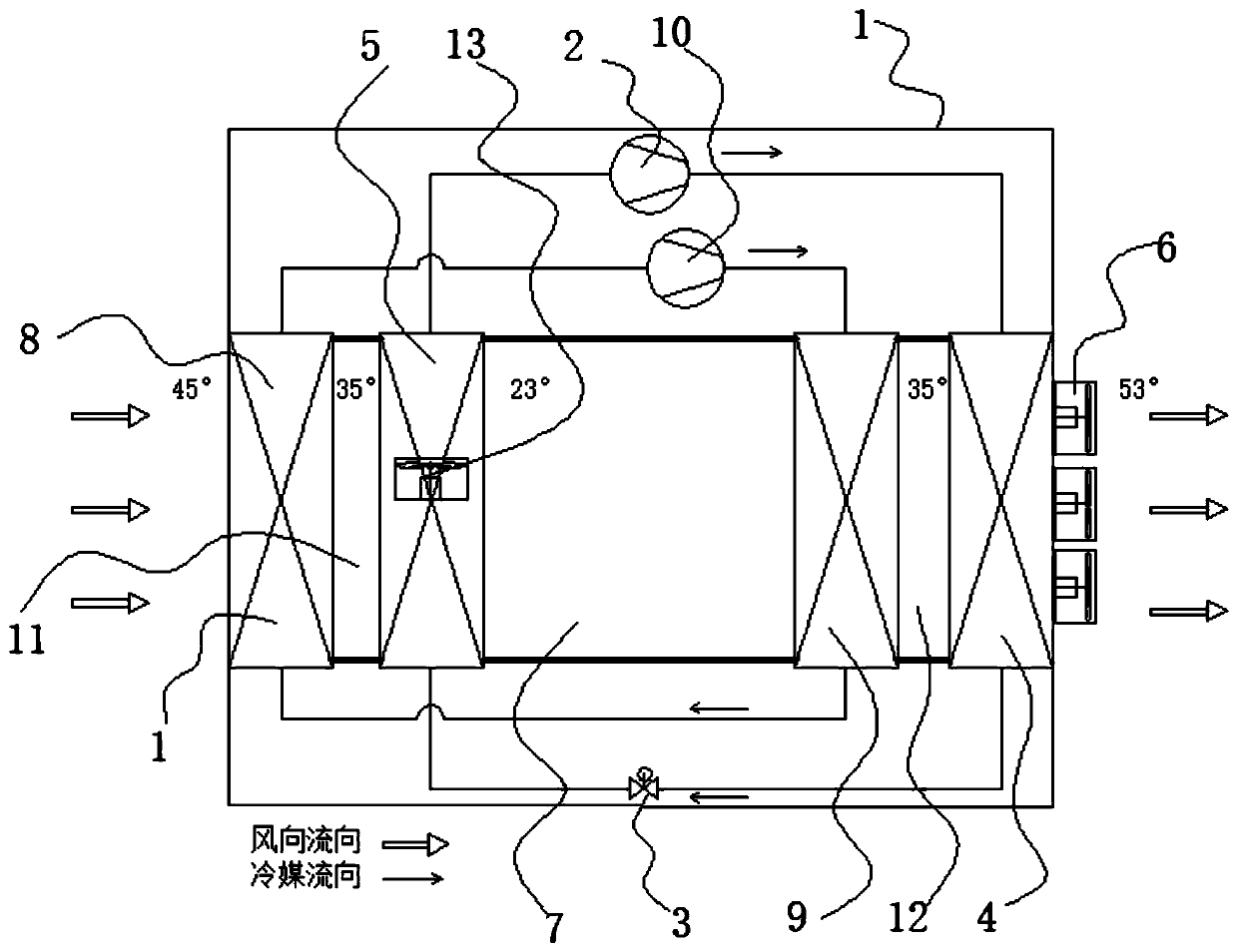
[0029] see figure 1 The high-performance air source drying and dehumidifying integrated machine provided in this embodiment includes a cabinet 1, a compressor 2, a throttle valve 3, a condenser 4, an evaporator 5, an air outlet fan 6 and a heat exchange device. The box body 1 is formed with an air passage 7, the condenser 4 and the evaporator 5 are respectively arranged at the front and rear sections of the air passage 7, and the air outlet fan 6 is arranged corresponding to the condenser 4 for exhausting air. The compressor 2 and the throttle valve 3 are respectively connected to the condenser 4 and the evaporator 5 to form a refrigerant flow cycle from the compressor 2 to the condenser 4 to the throttle valve 3 to the evaporator 5; the heat exchange device includes a pre-cooling Heat exchanger 8, preheating heat exchanger 9 and auxiliary compressor 10, described auxiliary compressor 10 is connected with precooling heat exchanger 8, preheating heat exchanger 9 through pipelin...

Embodiment 2

[0036] This embodiment is basically the same as Embodiment 1, the difference is that:

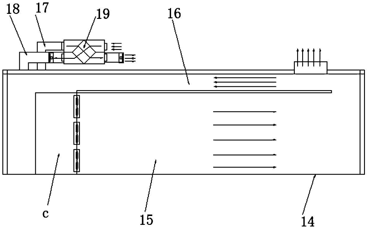
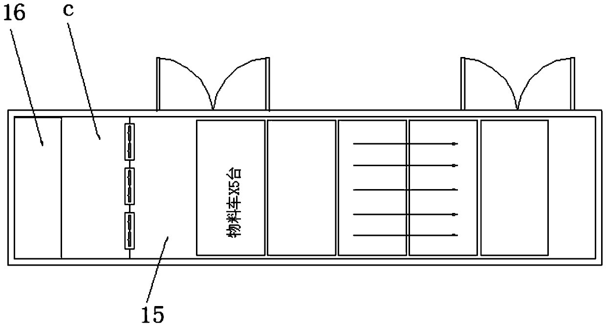
[0037] see Figure 4 to Figure 5 , using the dual-machine heat pump drying system of the high-performance air source drying and dehumidifying integrated machine, including a drying chamber 14, and the drying chamber 14 is provided with a separator 20 in the middle, thereby forming a left and right corresponding first A drying area 15a and a second drying area 15b. The drying chamber 14 is respectively provided with a first air return area 16a and a second air return area 16a connecting the first drying area 15a and the second drying area 15b at the front and rear positions. Wind area 16b, wherein, the front end of the first drying area 15a is provided with a first high-performance air source drying and dehumidifier c1, and the rear end of the second drying area 15b is provided with a second high-performance air source drying machine. The integrated drying and dehumidifying machine c2, the ...

Embodiment 3

[0042] see Image 6 , this embodiment is basically the same as Embodiment 1, the difference is that there is a height difference between the condenser 4 and the evaporator 5, and the position of the condenser 4 is higher than that of the evaporator 5, and the heat exchange The device includes a precooling heat exchanger 8, a preheating heat exchanger 9 and a gravity flow heat pipe 21, the precooling heat exchanger 8 corresponds to the evaporator 5, the preheating heat exchanger 9 corresponds to the condenser 4, and the preheating heat exchanger 9 corresponds to the condenser 4. There is a height difference between the cold heat exchanger 8 and the preheating heat exchanger 9, and the position of the preheating heat exchanger 9 is higher than that of the precooling heat exchanger 8, and the gravity self-flow heat pipe 21 and the precooling heat exchanger 8. The preheating heat exchangers 9 are connected to each other to form a loop, thereby forming a refrigerant flow cycle from...


PUM


Abstract

The invention discloses a high-performance air-source drying and moisture sucking integrated machine. The high-performance air-source drying and moisture sucking integrated machine comprises a box body, a compressor, a throttle valve, a condenser, an evaporator, a wind outlet fan and a heat exchanging device. According to the high-performance air-source drying and moisture sucking integrated machine disclosed by the invention, the structure of a conventional integrated straight type ventilation duct is improved; residual heat recycling is performed through precooling and preheating, and precooling and preheating cooperate with the evaporator and the condenser, so that large wind capacity is guaranteed, the dew-point temperature is higher, the moisture removing capacity is guaranteed, heatloss is reduced, heat utilization rate is increased, the stability and the uniformity of moisture removing and heating are guaranteed, and the integral drying effect and drying performance are improved. The invention also discloses a heat pump drying system adopting the high-performance air-source drying and moisture sucking integrated machine.

Description

technical field [0001] The invention relates to an air source integrated drying and dehumidifying technology, in particular to a high-performance air source drying and dehumidifying integrated machine and system. Background technique [0002] Most of the current air-source drying and dehumidifiers adopt a straight-through structure to improve air volume and heating efficiency, and also have a certain thermal uniformity performance. However, in the current straight-through structure, the return air directly passes through the evaporator, Although the condenser has a large air volume, the utilization rate of waste heat and the stability and uniformity of heating are not enough, and the overall effect needs to be improved. The applicant applied for an invention patent "An Air Source Integrated Drying and Dehumidifier and System" on 2017-06-12, the application number is 201710437006.9, the publication date is 2017-08-29, and the publication number is 107101471A. It discloses an...

Claims


Application Information

Patent Timeline
IPC IPC(8): F26B9/06F26B21/00F26B21/02F26B21/08F26B23/10F26B25/12
CPCY02P70/10
Inventor 朱文达邱新爱
Owner 东莞市科信新能源设备有限公司
Why Eureka
Try Eureka