
Permanent magnet synchronous motor deadbeat torque prediction control method
A permanent magnet synchronous motor, predictive control technology, applied in motor generator control, AC motor control, electronic commutation motor control and other directions, can solve the problems of complex algorithms and high requirements for digital controllers
- Summary
- Abstract
- Description
- Claims
- Application Information
AI Technical Summary
Problems solved by technology
Method used
Image

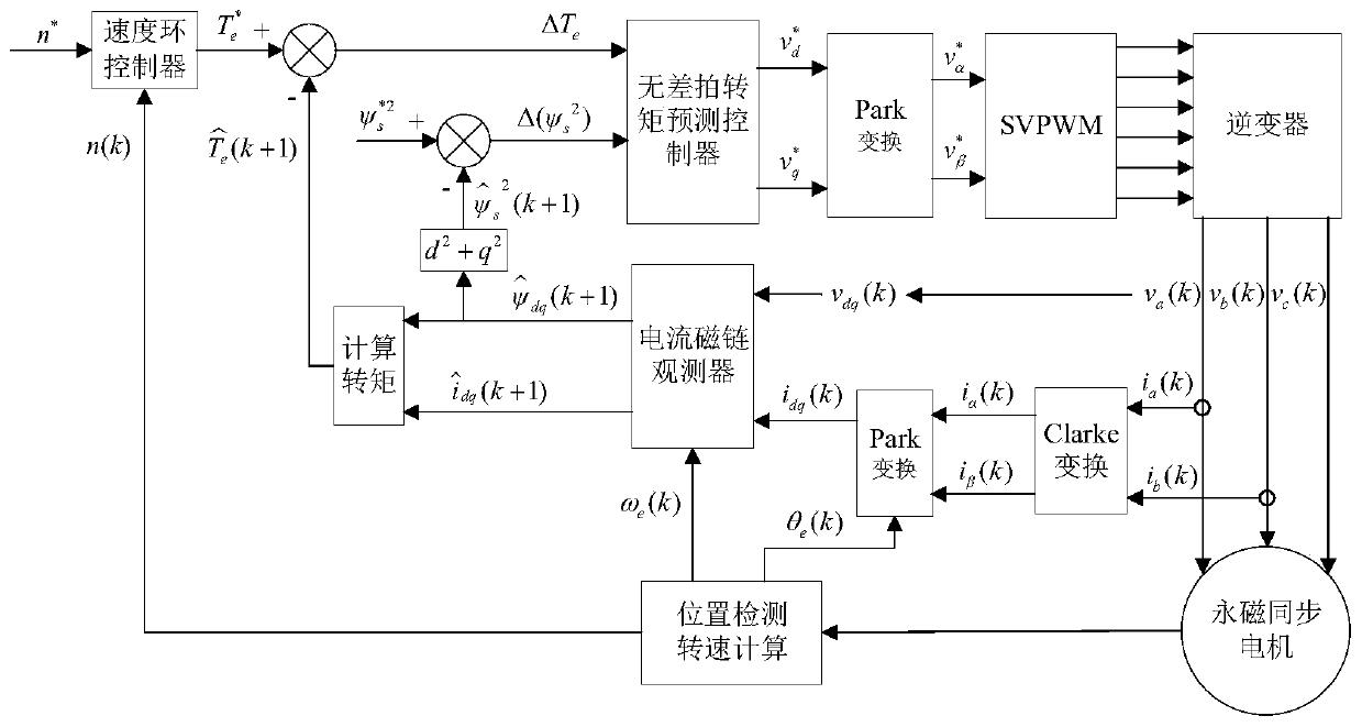
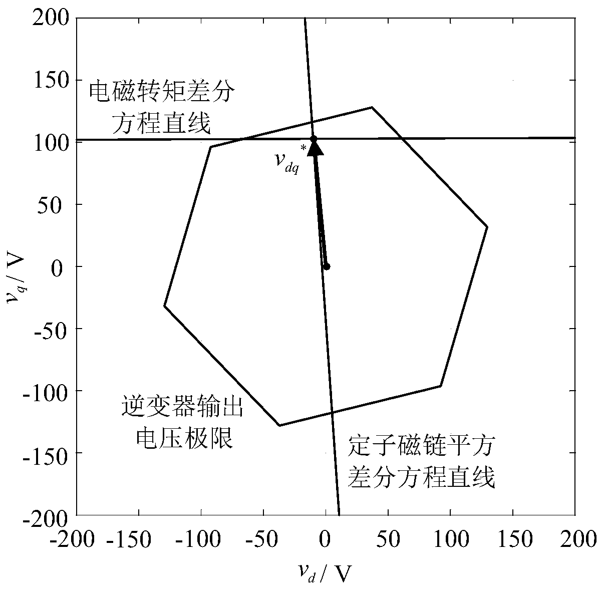
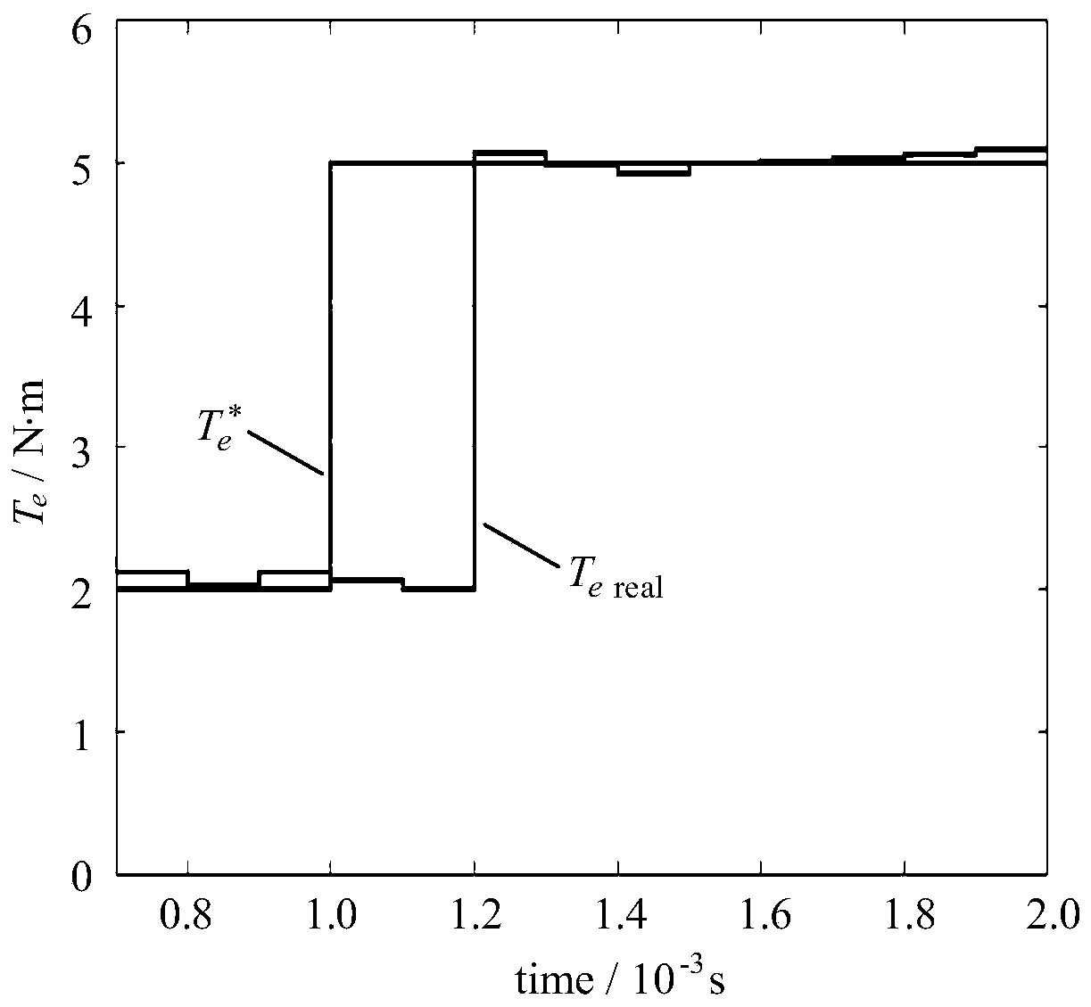
Examples
Embodiment Construction
[0062] The key technologies and specific implementation methods in the present invention will be described in detail below in conjunction with the drawings and specific embodiments.
[0063] A deadbeat torque prediction control method for a permanent magnet synchronous motor of the present invention, comprising the following steps:
[0064] 1. Define f dq =f d +j·f q , where j is an imaginary number unit, f can represent voltage v, current i and flux linkage ψ, the purpose is to use a single variable f dq conveniently expresses f d and f q .
[0065] 2. Obtain the phase current, phase voltage, and speed signal of the motor at the current sampling time (k time) (the actual speed of the rotor n(k) and the electrical angular velocity ω e (k)) and rotor position (θ e (k)), the phase voltage is more complex due to direct measurement, and generally can be directly calculated according to the control signal; the current of the motor in the synchronous rotating coordinate syste...
PUM
 Abstract
Description
Claims
Application Information