

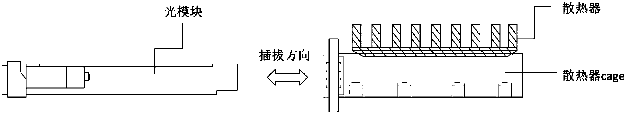
Compound thermal-conductive interface material and cooling structure in optical module plugging occasion
A technology of interface material and heat conduction material, which is applied in the field of communication, can solve the problems of incompatibility in performance, inability to fully meet the high heat conduction efficiency of equipment, and increased cost.
- Summary
- Abstract
- Description
- Claims
- Application Information
AI Technical Summary
Problems solved by technology
Method used
Image

Examples
Embodiment 1
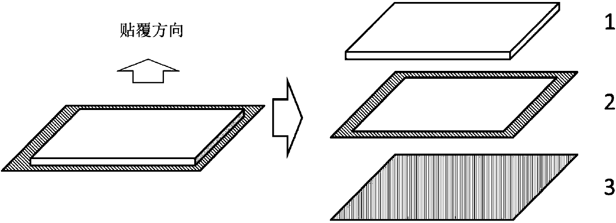
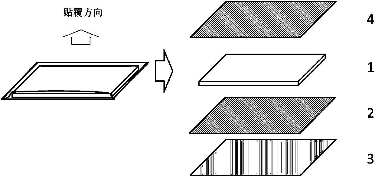
[0038] For scenarios that require insulation, choose a PI film with a thickness of 50 μm and thermal conductivity (thermal conductivity 0.78W / m K) as the wear-resistant layer, a thickness of 400 μm, a thermal conductivity of 2.3 W / m K, and self-adhesive The thermally conductive phase change material (PCM) is used as the thermally conductive layer, and the pressure-sensitive double-sided adhesive with a thickness of 5 μm is used as the adhesive layer, and the surrounding local adhesive is used, and the width is 5mm; The boss ends are arranged in sequence, thereby obtaining an ultra-thin plug-resistant composite thermal interface material.
[0039] The thermal simulation test platform is used to evaluate the improvement effect of this scheme on the heat dissipation of the device, and compare the PCM with a thickness of 400 μm without a wear-resistant layer structure, and the same structure but with a 200 μm PET film and a 400 μm thermal conductivity with a thermal conductivity of...
Embodiment 2
[0044] For the application scenarios without insulation requirements, choose aluminum foil with a thickness of 25 μm as the wear-resistant layer, PCM material with a thickness of 200 μm and a thermal conductivity of 2W / m K as the heat conduction layer, and a pressure-sensitive double-sided adhesive with a thickness of 10 μm as the adhesive layer , using local adhesive around the sides, with a width of 3mm; the above-mentioned thermally conductive layer, adhesive layer and wear-resistant layer are arranged sequentially from the boss end of the bottom surface of the radiator, thereby obtaining a composite thermally conductive interface material. Evaluate the improvement effect of this solution on the heat dissipation of the device through the thermal simulation test platform; select 9W as the input power, simulate the above application scenario, compare the temperature difference between the radiator and the heating device, and insert and unplug 200 times (plug force 30 ~ 40N) Th...
PUM
| Property | Measurement | Unit |
|---|---|---|
| Thermal conductivity | aaaaa | aaaaa |
| Thickness | aaaaa | aaaaa |
| Thermal conductivity | aaaaa | aaaaa |
Abstract
Description
Claims
Application Information