Light-transmitting enclosure structure with energy supply and energy storage functions

An enclosure structure and energy supply technology, applied in the field of energy saving, can solve the problems of inability to achieve household metering and independent control, high circulating energy consumption of water pumps, and large loss of water pump transportation energy, etc., to facilitate household metering and upgrading Insulation performance and thermal inertia, the effect of improving thermal storage performance

Pending Publication Date: 2019-06-11
TIANJIN UNIV OF COMMERCE
View PDF1 Cites 1 Cited by
  • Summary
  • Abstract
  • Description
  • Claims
  • Application Information

AI Technical Summary

Problems solved by technology

Although the system can reduce the temperature difference on both sides of the enclosure structure by supplying cooling water to reduce the energy consumption of air conditioning, the system is connected from the source end (cold source) to the end (shading structure) through a set of water circulation system. The reduction of temperature difference depends on the continuous circulation and supply of cooling water, resulting in high energy consumption of water pump circulation
Because the pipeline from the source end to the end is too long and the resistance is too large, the energy loss of the pump delivery is also relatively large
In addition, the system is a centralized energy supply system, which cannot realize household metering and independent control functions
The above disadvantages together lead to poor overall technical economy of the system

Method used


Image

  • Light-transmitting enclosure structure with energy supply and energy storage functions
  • Light-transmitting enclosure structure with energy supply and energy storage functions
  • Light-transmitting enclosure structure with energy supply and energy storage functions

Examples


Embodiment Construction

[0026] The present invention will be described in detail below in conjunction with the accompanying drawings and specific embodiments.

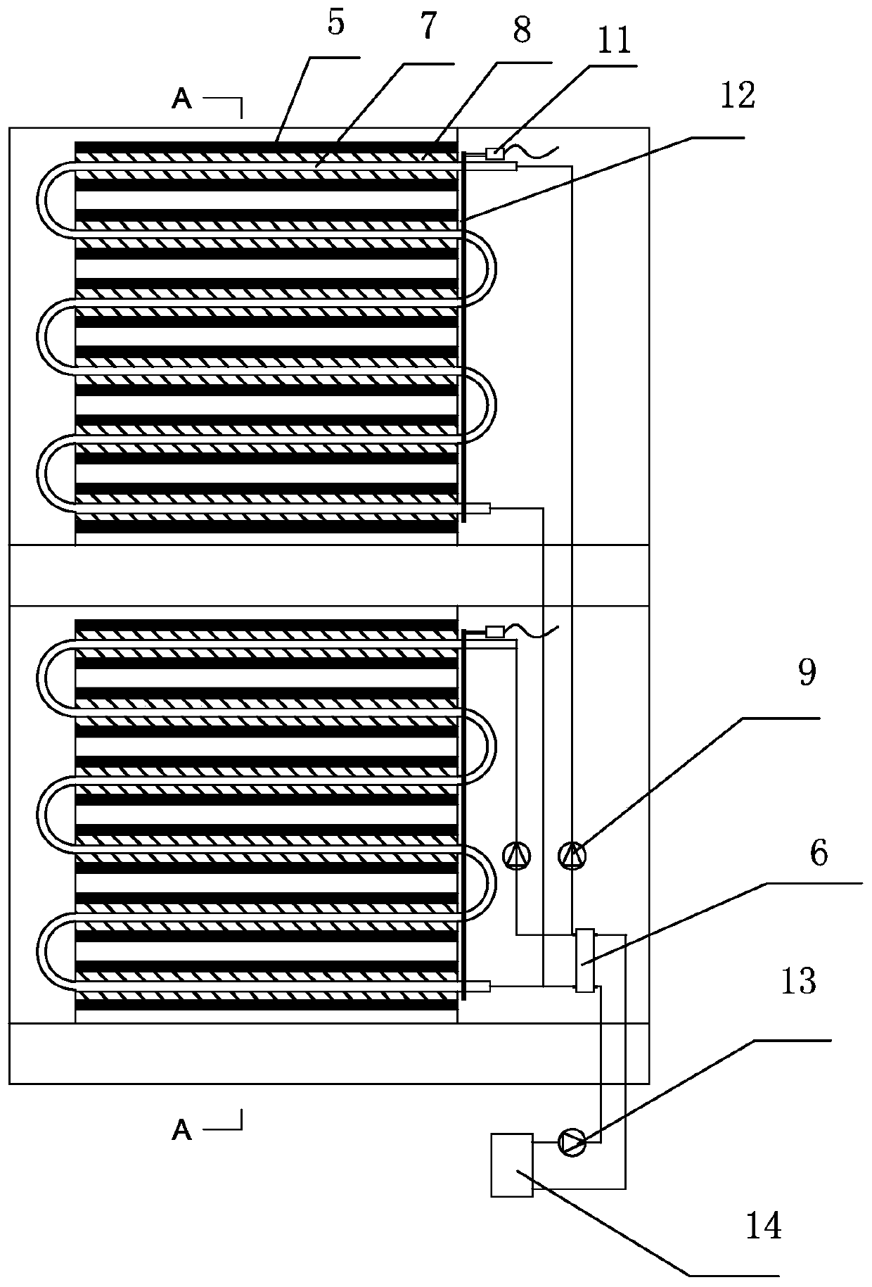
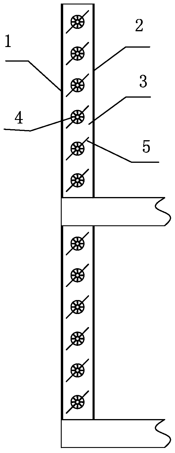
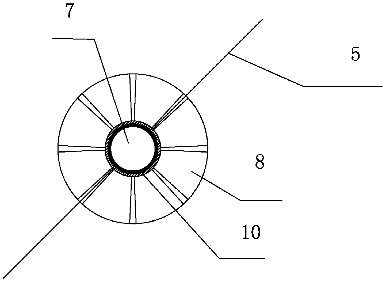
[0027] The schematic diagram of the light-transmitting enclosure structure with energy supply and energy storage functions of the present invention is as follows Figure 1-Figure 2 As shown, it includes a non-transparent wall, an active energy supply system at the source end, an intermediate heat exchange device 6 and an active energy supply and storage system at the end. The non-light-transmitting wall includes an outer light-transmitting layer 1 and an inner light-transmitting layer 2 , and an air cavity 3 is formed between the inner light-transmitting layer 2 and the outer light-transmitting layer 1 . The source end active energy supply system includes a source end cold and heat source device 14 and a source end water pump 13. The source end cold and heat source device 14 and the source end water pump 13 are connected with the intermediate...


PUM


Abstract

The invention discloses a light-transmitting enclosure structure with energy supply and energy storage functions. The nighttime valley electricity moment is fully utilized for energy storage, and theoperating cost is reduced. The light-transmitting enclosure structure comprises a non-light-transmitting wall, a source end active energy supply system, an intermediate heat exchange device and a tailend active energy supply and storage system; the source end active energy supply system comprises a source end cold and heat source device and a source end water pump, the source end cold and heat source device, the source end water pump and the intermediate heat exchange device communicate with each other to form a source end energy supply cycle, and the tail end active energy supply and storagesystem includes at least one set of active heat exchange energy storage unit and a tail end circulating power device; the active heat exchange energy storage unit comprises a heat exchange unit formed by communicating heat exchange pipes and an energy storage chamber arranged outside the heat exchange pipes, and the active heat exchange energy storage unit is placed in an air chamber; and the active heat exchange energy storage unit, the tail end active energy supply and storage system and the intermediate heat exchange device communicate with each other to form a tail end heat exchange energy storage cycle. By means of the system, the heat transfer temperature difference between the inner surface of the enclosure structure and the indoor place can be reduced, and the running cost is reduced.

Description

technical field [0001] The invention relates to the technical field of energy saving, in particular to a light-transmitting enclosure structure system with energy supply and energy storage functions. Background technique [0002] Envelope structures are mainly divided into two categories: light-transmitting envelope structures and non-light-transmitting envelope structures. Due to its beautiful appearance, the light-transmitting enclosure structure is favored by architectural designers and users. Due to the larger heat transfer coefficient of the light-transmitting enclosure structure than that of the thermal insulation wall, and the relatively small heat capacity of the light-transmitting enclosure structure, the thermal resistance and thermal inertia (heat storage performance) of the light-transmitting enclosure structure are relatively poor, resulting in energy Consumption is always high. [0003] At present, researchers mainly reduce the heat transfer coefficient of th...

Claims


Application Information

Patent Timeline
Patent Type & Authority Applications(China)
IPC IPC(8): F28D15/02F28F9/00
Inventor 律宝莹杨洋陈萨如拉
Owner TIANJIN UNIV OF COMMERCE
Why Eureka
Try Eureka