Optical flow control cell sorting chip and method

A technology of optofluidics and cells, applied in the field of optofluidics, can solve the problems of high economic cost and time cost, difficult simultaneous manipulation and separation of cells, difficult microfluidic chip combination, etc., to achieve low cost of experimental equipment and enhanced application Field, mobility strong effect

Active Publication Date: 2019-06-14
SOUTH CHINA NORMAL UNIVERSITY
View PDF17 Cites 9 Cited by
  • Summary
  • Abstract
  • Description
  • Claims
  • Application Information

AI Technical Summary

Problems solved by technology

However, traditional optical tweezers have several shortcomings: First, the excitation equipment is large and complex, expensive and has a large loss
Therefore, the preparation and maintenance of the experimental platform require high economic and time costs
Second, it cannot be flexibly controlled, and it is dif

Method used


Image

  • Optical flow control cell sorting chip and method
  • Optical flow control cell sorting chip and method
  • Optical flow control cell sorting chip and method

Examples


Embodiment 1

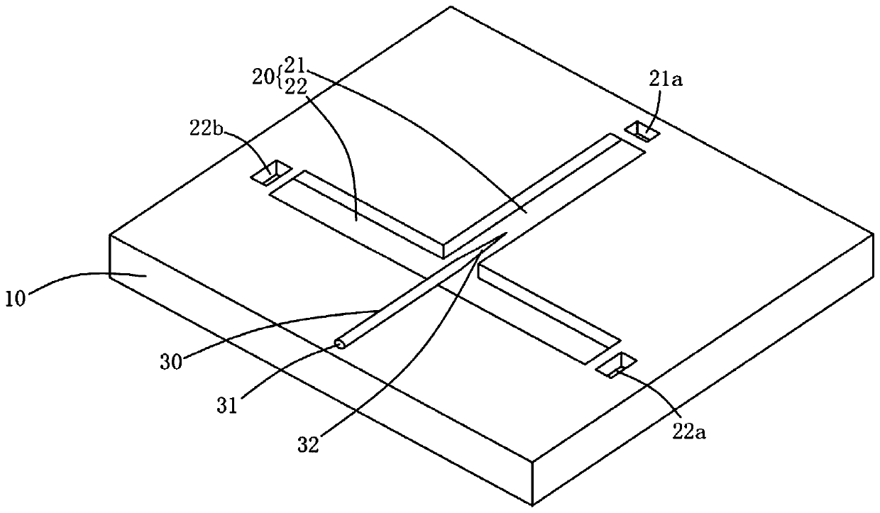
[0049] Such as figure 1As shown, the optofluidic cell sorting chip according to Embodiment 1 of the present invention includes a substrate 10, a microfluidic channel 20 and an optical waveguide 30, wherein the microfluidic channel 20 is arranged in the substrate 10, and the optical waveguide 30 is movably arranged in the on substrate 10. The microfluidic channel 20 at least includes a first channel 21 and a second channel 22 communicating with each other, the first channel 21 and the second channel 22 are both used to accommodate microfluids, and the first channel 21 is also used to accommodate at least two kinds of cells. The optical waveguide 30 includes an optical signal input end 31 and a capture end 32, the optical signal input end 31 is used for receiving an optical signal, the capture end 32 is used for adsorbing one of the at least two types of cells, and the capture end 32 is used for absorbing The cells move into the second channel 22. As a preferred embodiment, th...

Embodiment 2

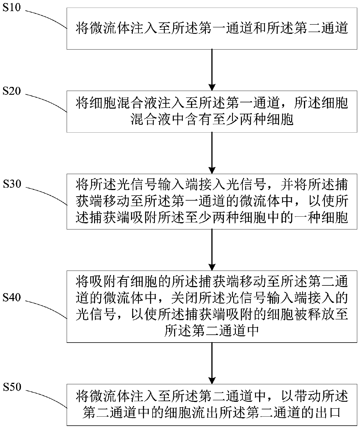
[0055] Such as figure 2 As shown, the method for sorting cells based on an optofluidic cell sorting chip according to Embodiment 2 of the present invention includes the following steps:

[0056] Step S10 : injecting microfluid into the first channel 21 and the second channel 22 .

[0057] Specifically, the microfluid is injected from the first inlet 21a by using a syringe pump, so that the microfluid is filled with the first channel 21 and the second channel 22 . Among them, microfluidics can use fluids that are harmless to biological cells, including deionized water and PBS buffer water.

[0058] Step S20: inject the cell mixture into the first channel 21, the cell mixture contains at least two kinds of cells.

[0059] Specifically, the cell mixture is injected from the first inlet 21 a through a syringe pump, so that the cell mixture is distributed in the first channel 21 .

[0060] Step S30: Connect the optical signal input end 31 to the optical signal, and move the cap...


PUM

PropertyMeasurementUnit
Melting pointaaaaaaaaaa
Wavelengthaaaaaaaaaa
Diameteraaaaaaaaaa

Abstract

The invention discloses an optical flow control cell sorting chip and method. The chip comprises a substrate, a microfluidic channel and an optical waveguide. The microfluidic channel is disposed in the substrate, and the optical waveguide is movably disposed on the substrate. The microfluidic channel comprises at least a first channel and a second channel which are mutually communicated, the first channel and the second channel are both used for accommodating microfluidics, and the first channel is further used for accommodating at least two kinds of cells. The optical waveguide comprises anoptical signal input end and a capture end. The optical signal input end is used for accessing an optical signal, the capture end is used for adsorbing one of at least two kinds of cells, and the capture end is used for releasing the adsorbed cells to the second channel. The chip is simple in structure and manufacturing method, low in cost, capable of sorting micro-nano cells accurately efficiently and flexibly by using the cone waveguide and capable of separating unmarked biological cells.

Description

technical field [0001] The invention belongs to the field of optofluidic technology, and in particular relates to an optofluidic cell sorting chip and a method for sorting cells thereof. Background technique [0002] Cell sorting is the basis of biological research and clinical diagnosis, and plays a vital role in the fields of single cell analysis, disease detection and diagnosis. Traditional cell sorting methods mainly include fluorescence activated cell sorting, dielectrophoresis sorting and magnetophoretic sorting. However, the above methods require additional biochemical markers, large sample volumes, high electric and magnetic fields, etc., which greatly limit the further application of cell sorting in the isolation of label-free, rare living cells. In 1987, Ashkin et al. proposed in "Science" that optical tweezers can manipulate micro / nano particles or living cells in fluid media without physical contact by focusing light beams. However, traditional optical tweezers...

Claims


Application Information

Patent Timeline
IPC IPC(8): C12M1/42C12M1/00C12N13/00C12N5/078C12N5/09C12N1/20C12R1/445C12R1/19
Inventor 邢晓波刘绍静翁哲李宗宝陈伊琳吴家隐杨剑鑫周瑞雪薛盛
Owner SOUTH CHINA NORMAL UNIVERSITY
Why Eureka
Try Eureka