Spiral type variable capacity buffer and work method thereof
A buffer, screw technology, applied in the direction of shock absorbers, shock absorbers, liquid shock absorbers, etc., can solve the problems of inability to automatically adjust the buffer resistance, uncontrollable buffer process, unstable buffer process, etc., to achieve rapid adjustment , the effect of fast response and large buffer range
- Summary
- Abstract
- Description
- Claims
- Application Information
AI Technical Summary
Problems solved by technology
Method used
Image

Examples
Embodiment 1
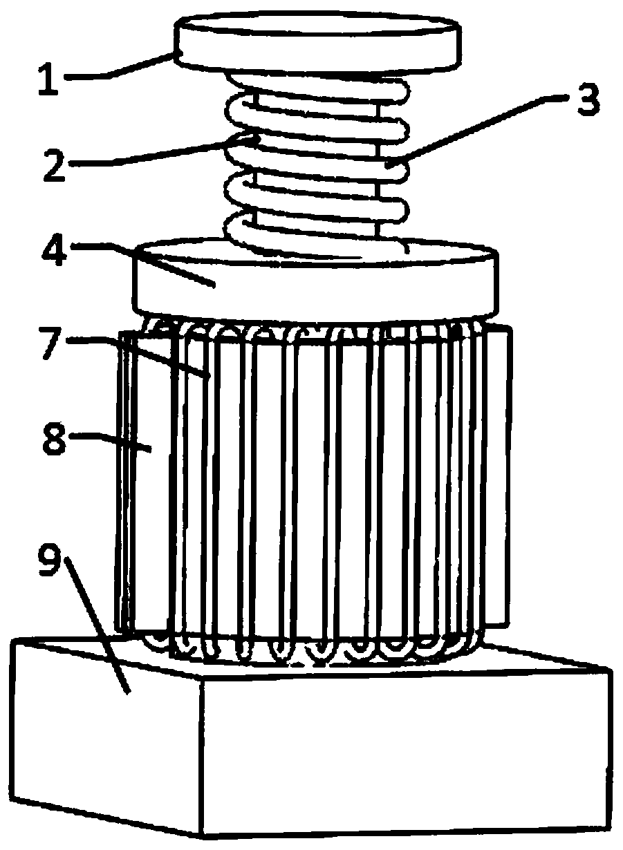
[0049] Such as Figure 1 to Figure 6 As shown, the present embodiment provides a spiral variable capacity buffer, which includes a cylinder body 6, a first piston 5, a first piston rod 2, a striker 1 and a valve block 9;
[0050] Wherein the first piston 5, the first piston rod 2 and the striker 1 are sequentially connected, the first piston 5 is located in the cylinder body 6 and encapsulates the cylinder body 6 through the first end cover 4, and the first piston 5 is provided with a spiral groove, A magnetically controlled shape memory alloy block is installed in the spiral groove; the first piston 5 divides the inner chamber of the cylinder 6 into an upper chamber A and a lower chamber B;
[0051] A first return spring 3 is set on the first piston rod 2 between the bumper 1 and the first end cover 4, an electromagnetic coil 7 is arranged on the outer periphery of the cylinder body 6, and a valve block 9 is connected to the bottom of the cylinder body 6;
[0052] The valve bl...
Embodiment 2
[0057] A spiral variable capacity buffer, the structure of which is as described in Embodiment 1, the difference is that: the spiral grooves are multi-head parallel grooves, and the multi-head parallel grooves are evenly distributed on the surface of the first piston 5 . The magnetically controlled shape memory alloy block is distributed in each wire groove around a circumference.
Embodiment 3
[0059] A working method of a spiral variable capacity buffer, comprising the following steps:
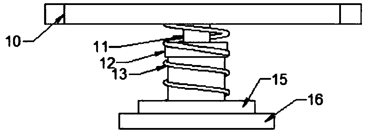
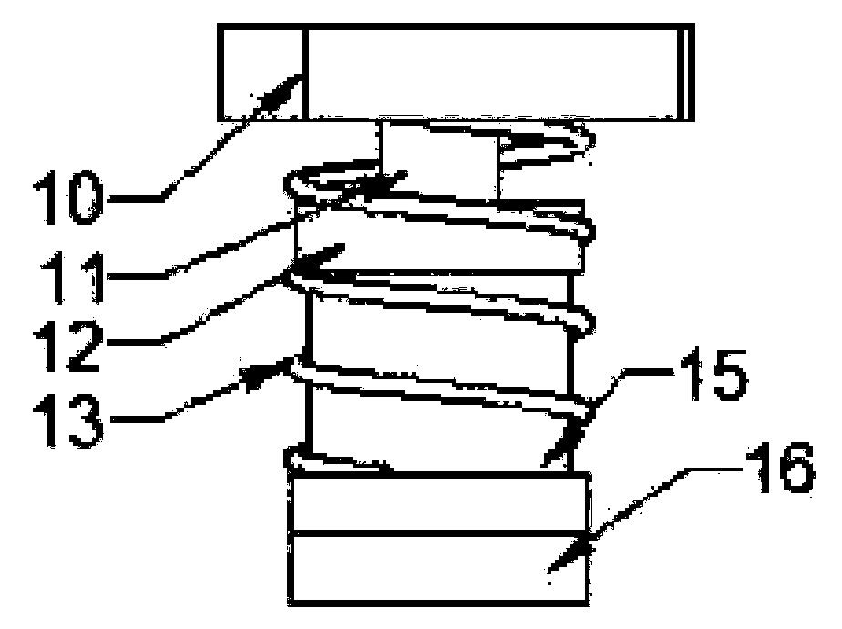
[0060] (1) When the impact head 1 is impacted, the first piston rod 2 moves down, and at the same time the pressure sensor detects the pressure change and transmits the pressure signal to the controller. The controller controls the power supply to adjust to the electromagnetic The size of the coil 7 power supply current, so as to achieve the adjustment of the field intensity generated by the electromagnetic coil 7;
[0061] (2) The electromagnetic coil 7 adjusts the magnetically controlled shape memory alloy block through different field strengths, thereby adjusting the capacity of the helical groove; that is, when the pressure sensor transmits a pressure signal that becomes smaller, the field strength generated by the electromagnetic coil 7 becomes larger, The second piston rod 11 in the magnetically controlled shape memory alloy block on the helical groove is stretched out, and th...
PUM
 Abstract
Description
Claims
Application Information