Large-load and high-frequency in-situ tension and fatigue tester based on X-ray imaging

A fatigue testing machine and in-situ stretching technology, applied in the direction of applying stable tension/compression to test the strength of materials, using radiation for material analysis, and using applied repetitive force/pulsation force to test the strength of materials, etc., can solve the problem that cannot be exerted Advanced light source detection capabilities, inability to test and characterize high-strength materials, long loading time and other issues, to achieve long life, high load, and fast frequency response

Pending Publication Date: 2019-06-14
SOUTHWEST JIAOTONG UNIV
View PDF1 Cites 4 Cited by
  • Summary
  • Abstract
  • Description
  • Claims
  • Application Information

AI Technical Summary

Problems solved by technology

However, worldwide research on in-situ imaging loading mechanisms based on high-energy X-ray imaging still cannot meet people's urgent needs for new high-performance materials and service behavior evaluation, for example, combining synchrotron radiation X-rays to penetrate materials with different densities Capacity, for high-strength aluminum alloys, the peak force of low-cycle fatigue loading of 2mm diameter samples is above 1500N; for additive manufacturing of titanium alloys, the monotonic tensile loading force of 2mm diameter samples is above 3500N
It can be seen that the current in-situ fatigue testing machine with a loading force of less than 1000N will cause the sample size to be too small, and the loading time will be long, and even high-strength materials cannot be tested and characterized, and the excellent detection ability of advanced light sources cannot be exerted.

Method used


Image

  • Large-load and high-frequency in-situ tension and fatigue tester based on X-ray imaging
  • Large-load and high-frequency in-situ tension and fatigue tester based on X-ray imaging
  • Large-load and high-frequency in-situ tension and fatigue tester based on X-ray imaging

Examples


Embodiment Construction

[0034] The present invention will be described in detail below in conjunction with the accompanying drawings.

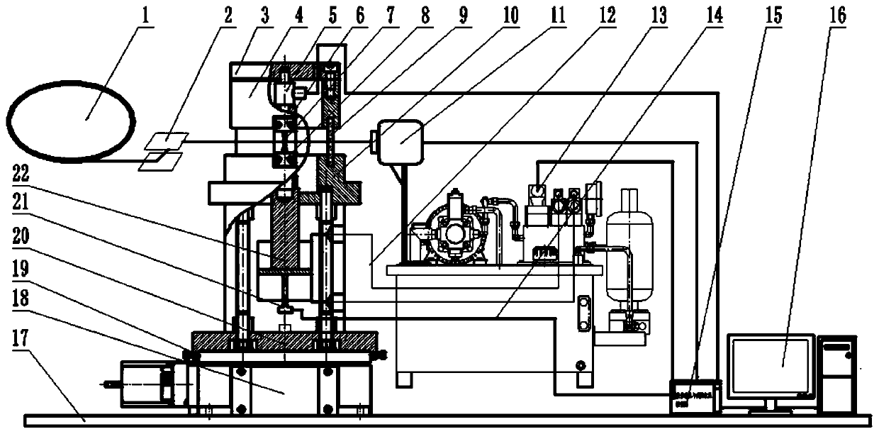
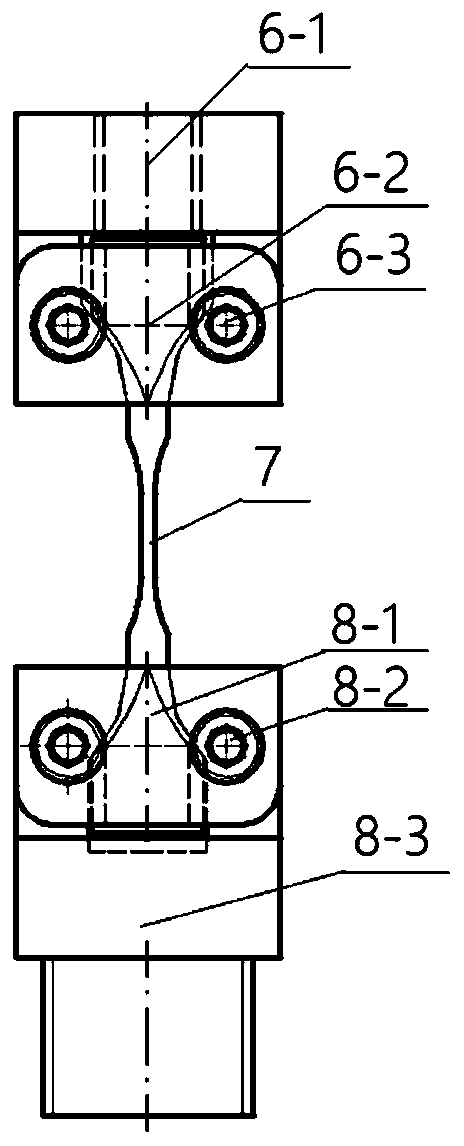
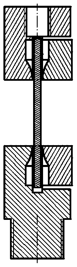
[0035] In the figure, 1 is the synchrotron radiation light source, 2 is the monochromator, 3 is the top cover, 4 is the support cylinder, 5 is the load sensor, 6 is the upper fixture, 7 is the sample, 8 is the lower fixture, and 9 is the transparent enclosure , 10 is a light source experiment platform, 11 is an X-ray detector, 12 is a hydraulic oil pipe, 13 is an electro-hydraulic servo valve, 14 is a hydraulic station, 15 is a data acquisition and controller (that is, a data acquisition and control unit), 16 is a data processing unit, 17 is a light source experiment platform, 18 is an imaging translation stage, 19 is a locking screw, 20 is a testing machine base, 21 is a displacement sensor, and 22 is a servo hydraulic cylinder.

[0036] figure 1 Shown is a large-load high-frequency in-situ tensile and fatigue testing machine based on X-ray imaging, which includes ...


PUM


Abstract

The invention discloses a large-load and high-frequency in-situ tension and fatigue tester based on X-ray imaging. An imaging displacement stage can be rotatably mounted on a test platform; a base isfixed on the imaging displacement stage, a rack is arranged on the base, a servo hydraulic cylinder is arranged on the rack, a lower clamp is rotatably connected to an upper end of a piston rod of thehydraulic cylinder, a support seat platform is fixed on four uprights of the rack; a support tube is located at an upper side of the support seat platform, a transparent cover is embedded between thesupport seat platform and the support tube; an upper clamp is fixed on the support tube; an electrolyte servo valve is connected with an upper oil chamber and a lower oil chamber of the hydraulic cylinder; a load sensor, the electrolyte servo valve and a X-ray detector are orderly connected with a data collection and control unit and a data processing unit. The tester disclosed by the invention has the features of being large in load, high in frequency, small in volume, and high in precision.

Description

technical field [0001] The invention relates to a fatigue test device for performing mechanical tests on materials, in particular to a large-load, high-frequency, high-precision in-situ tensile and fatigue testing machine for three-dimensional imaging using high-energy X-rays. Background technique [0002] Fatigue of materials and structures has been a key topic of long-term concern in the academic and engineering circles. Traditional methods such as destructive slicing and fracture identification are used to deduce the failure modes, paths and mechanisms of materials and structures based on the obtained microstructure evolution, which is not only time-consuming It is laborious, and the observation results are limited to the representative surface of the representative material, so it is difficult to reflect the local damage characteristics in the range of large-volume materials, especially the damage nucleation and growth process cannot be observed in situ, real-time and dyn...

Claims


Application Information

Patent Timeline
IPC IPC(8): G01N3/12G01N3/36G01N23/04
Inventor 吴圣川吴正凯谢成宋哲鲍泓翊玺胡雅楠康国政刘宇杰
Owner SOUTHWEST JIAOTONG UNIV
Why Eureka
Try Eureka