Fabricated corrugated steel plate shear wall structure and construction method thereof

A steel plate shear wall and corrugated technology, applied in the direction of walls, building components, building types, etc., can solve the problems of easy cracking, brittleness of the wall, increased reinforcement and maintenance costs, and affecting normal use status, etc., to achieve light weight , Simple structure, good deformation ability

Pending Publication Date: 2019-06-18
CENT SOUTH UNIV
View PDF6 Cites 2 Cited by
  • Summary
  • Abstract
  • Description
  • Claims
  • Application Information

AI Technical Summary

Problems solved by technology

Traditional shear wall materials often use reinforced concrete. In order to be able to withstand large lateral loads and meet design requirements, the wall section is often wide, and more shear steel bars need to be configured. After pouring, it is heavy and heavy.
And because a lot of shear steel bars are arranged in it, it brings great inconvenience to the subsequent construction and seriously affects the progress of the construction.
For the traditional reinforced concrete shear wall, after the pouring is completed, the wall is also prone to cracking and brittle damage under the joint action of large lateral load and concrete self-shrinkage and creep; this not only affects Its existing normal use status also increases its subsequent reinforcement and maintenance costs
[0003] In recent years, with the rise of prefabricated building structures, although many prefabricated shear walls mainly reinforced concrete shear walls have been proposed and produced in the industry, they still have problems such as easy cracking, self-heavy weight, and low energy consumption. Defects such as good, non-recoverable after damage

Method used


Image

  • Fabricated corrugated steel plate shear wall structure and construction method thereof
  • Fabricated corrugated steel plate shear wall structure and construction method thereof
  • Fabricated corrugated steel plate shear wall structure and construction method thereof

Examples


Embodiment Construction

[0033] The invention will be further described in detail below in conjunction with the accompanying drawings and specific embodiments.

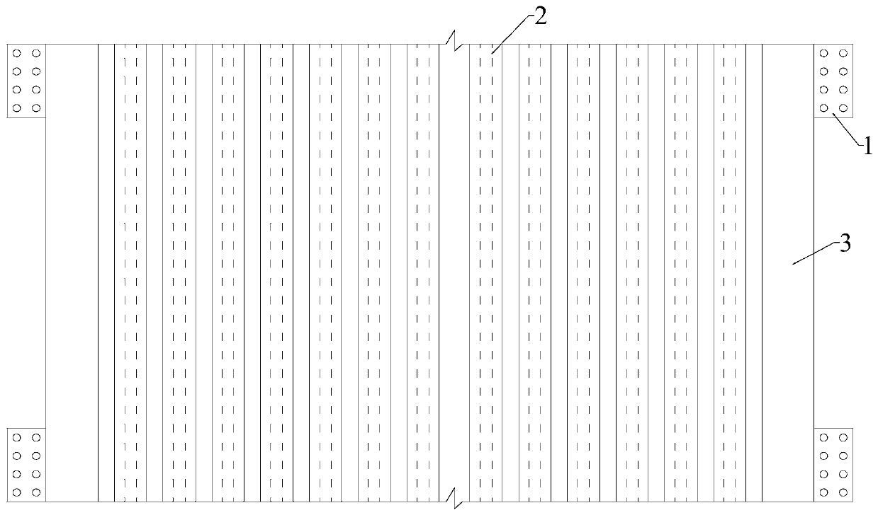
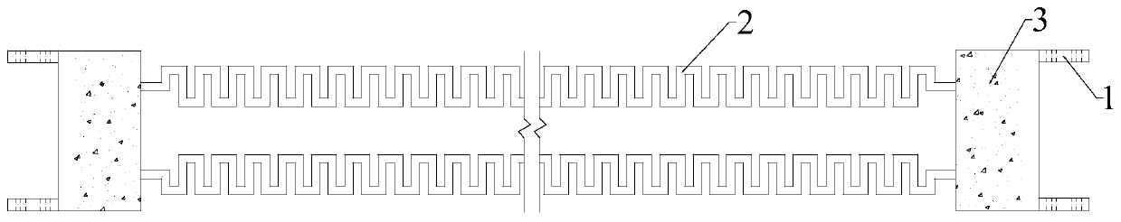
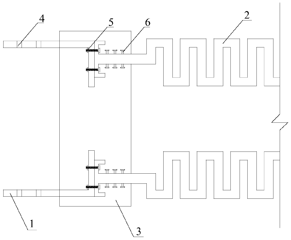
[0034] Such as Figure 1-3 As shown, an assembled corrugated steel plate shear wall structure includes a corrugated steel plate shear wall 2, an end reinforced concrete connection block 3, and an L-shaped bolt steel plate connector 1; the shear wall structure consists of two Composed of corrugated steel plates, the two ends of the two corrugated steel plates are T-shaped, and shear keys 6 are arranged on both sides of the ends;

[0035] In this example, both ends of the corrugated steel plate are provided with shear keys on both sides, and the embedded length thereof is 1 / 2 to 3 / 5 times the width of the concrete connecting block. The shear keys are arranged in a matrix on the surface of both ends of the steel plate, wherein they are evenly arranged at intervals of 10-20 cm along the vertical direction of the wall, and evenly distributed at i...


PUM


Abstract

The invention discloses a fabricated corrugated steel plate shear wall structure and a construction method thereof. The fabricated corrugated steel plate shear wall structure includes a shear wall, arebar concrete connecting block, and a connecting part, wherein the shear wall is formed by horizontally arranging two corrugated steel plates, the rebar concrete connecting block is installed on theend part of the shear wall and the two corrugated steel plates are fixed by the rebar concrete connecting block to a whole, and the connecting part is prefabricated in the rebar concrete connecting block and is used for connecting with adjacent members; and a steel plate part, prefabricated in the rebar concrete connecting block, of the corrugated steel plates is in a T shape, a plurality of shearkeys are welded to the two sides of the corrugated steel plate T-shaped part, and composite novel anti-rust coating products are painted on the surfaces of the corrugated steel plates and the connecting part. According to the fabricated corrugated steel plate shear wall structure and the construction method thereof, the used corrugated steel plates have the characteristics of being good in anti-corrosion performance, high in horizontal shearing resistance strength, and good in energy-dissipating capacity, and former traditional cumbersome rebar concrete shear walls are replaced.

Description

technical field [0001] The invention relates to an assembled corrugated steel plate shear wall structure and a construction method thereof, belonging to the field of civil engineering. Background technique [0002] Shear walls are mainly used in houses or structures to withstand lateral loads under wind loads or earthquake loads to prevent structures from shearing damage, so they are also called wind-resistant walls and earthquake-resistant walls. Shear wall structures are widely used in high-rise and super high-rise buildings. Traditional shear wall materials often use reinforced concrete. In order to be able to withstand large lateral loads and meet the design requirements, the wall section is often wide, and more shear steel bars need to be configured. After pouring, it is heavy and heavy. And because a lot of shear steel bars are arranged in it, it brings great inconvenience to the follow-up construction and seriously affects the progress of construction. For the tradi...

Claims


Application Information

Patent Timeline
Patent Type & Authority Applications(China)
IPC IPC(8): E04B2/00E04B1/38E04B1/41E04B1/98E04H9/02
Inventor 罗小勇程俊峰申智勇李玲玲唐伟明
Owner CENT SOUTH UNIV
Why Eureka
Try Eureka