
Visual inertia odometer based on hardware accelerator

A hardware accelerator and odometer technology, which is applied in the field of visual inertial odometer, can solve the problems of easy drift of VIO and mismatch of key frame data frequency, etc., and achieve the effect of reducing conversion calculation, reducing time complexity and fast detection speed

Inactive Publication Date: 2019-06-18
AUTOCORE INTELLIGENT TECH NANJING CO LTD
View PDF2 Cites 1 Cited by
  • Summary
  • Abstract
  • Description
  • Claims
  • Application Information

AI Technical Summary

Problems solved by technology

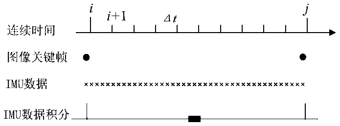
[0006] In order to solve the problem of data frequency mismatch between IMU, image frame, and key frame, this method pre-integrates the IMU information between key frames, and then combines the conventional visual SLAM method to improve the accuracy of VIO.

Method used


Image

  • Visual inertia odometer based on hardware accelerator
  • Visual inertia odometer based on hardware accelerator
  • Visual inertia odometer based on hardware accelerator

Examples


Embodiment

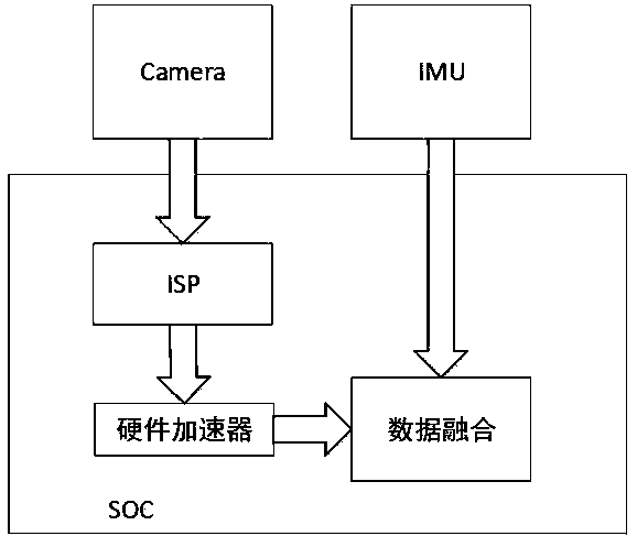
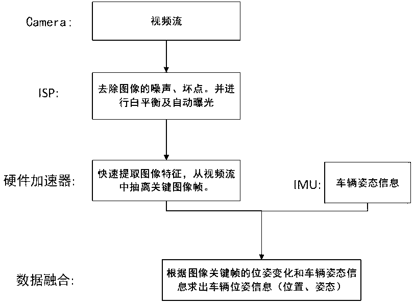
[0028] The visual-inertial odometry hardware platform based on the hardware accelerator of the present embodiment is as figure 1 As shown, the platform is mainly composed of car-grade SOC, Camera, and IMU. The image signal processor and hardware accelerator in the SOC process the image information output by the Camera, detect the feature points in the image, and find the adjacent key frames. The IMU can measure the acceleration and angular velocity information of the vehicle in real time. The current position information of the vehicle relative to the starting point is calculated by fusing the key frame data of the image and the body state information of the IMU. In order to solve the problem of data frequency mismatch between IMU, image frame, and key frame, this method pre-integrates the IMU information between key frames, and then combines the conventional visual SLAM method to improve the accuracy of VIO. Use hardware acceleration chips to extract image features in VIO, ...


PUM


Abstract

The invention provides a visual inertia odometer based on a hardware accelerator. The visual inertia odometer installed on an autonomous driving vehicle comprises an embedded hardware platform, a camera and an inertial measurement unit. An image signal processor and a hardware accelerator are arranged in the embedded hardware platform; the image signal processor is used for processing image information acquired by the camera; the inertial measurement unit measures the vehicle body state information of the vehicle in real time; and the hardware accelerator is used for detecting feature points in the image information, calculating adjacent key frames, carrying out data fusion on the key frames as the starting and ending points and the vehicle body state information, and calculating current position information of the relative starting point of the vehicle. According to the invention, the vehicle-level SOC with the image signal processor and hardware accelerator is used for processing image data and the data are combined with IMU input data, so that the processing efficiency and precision are high. Besides, the embedded platform has characteristics of high stability, great easiness inmounting, and low power consumption and is suitable for the r autonomous driving technology.

Description

technical field [0001] The invention relates to inertial navigation and an instrument for performing navigation calculations, in particular to a visual inertial odometer based on a hardware accelerator in the field of automatic driving. Background technique [0002] Visual-inertial odometry (visual-inertial odometry, VIO) is a vehicle trajectory tracking and real-time positioning method realized by fusing camera and IMU data. It mainly consists of a monocular or binocular camera and an inertial measurement unit (IMU). The sensor fusion algorithm can solve the instability of a single sensor such as the zero bias of the IMU and the sensitivity to visual light. Compared with laser scanning radar, vision sensors have a significant price advantage and should have a wider range. [0003] The currently commonly used VIO fusion method performs data fusion on the IMU information between image frames. The detection efficiency and detection accuracy of feature points in the visual fr...

Claims


Application Information

Patent Timeline
IPC IPC(8): G01C22/00G06K9/00
Inventor 李赵刘心刚陈诚张旸
Owner AUTOCORE INTELLIGENT TECH NANJING CO LTD
Learn More