
Composite material dynamic fatigue testing device and method based on reverse resonance

A composite material and test device technology, which is applied in measuring devices, analyzing materials, and analyzing solids using sound waves/ultrasonic waves/infrasonic waves, etc., can solve the lack of research capabilities of fatigue performance of new composite materials, the inability to carry out dynamic fatigue tests, and low test frequency and other issues to achieve the effect of improving test efficiency, broadening the amplitude range, and saving energy

Inactive Publication Date: 2019-06-18
NORTHEASTERN UNIV
View PDF12 Cites 3 Cited by
  • Summary
  • Abstract
  • Description
  • Claims
  • Application Information

AI Technical Summary

Problems solved by technology

Patent CN 107966354 A uses laminated unidirectional plates to measure the fatigue of composite materials, and provides a fatigue life prediction method, device and electronic equipment for composite materials, but it relies too much on the support of existing databases, and the fatigue performance of new composite materials Insufficient research capacity
The electro-hydraulic servo method can achieve large load loading, but the work efficiency is low
Electromagnetic resonance method, the use of electronic control technology can achieve the purpose of energy saving, but the amplitude is small, and it is not easy to control
[0004] With the widespread use of fiber-reinforced composite materials, although the traditional universal material testing machine can evaluate the material to a certain extent, such as separate static loads such as tension, compression, and torsion can be applied to the material, and this evaluation The influence of force on fatigue characteristics, the test frequency is very low (about 3~10Hz) and dynamic fatigue test cannot be carried out
The universal material testing machine has great limitations and is not suitable for the measurement and evaluation of the fatigue properties of fiber-reinforced composite materials at this stage

Method used


Image

  • Composite material dynamic fatigue testing device and method based on reverse resonance
  • Composite material dynamic fatigue testing device and method based on reverse resonance
  • Composite material dynamic fatigue testing device and method based on reverse resonance

Examples


Embodiment Construction

[0036] It should be noted that all directional indications (such as up, down, left, right, front, back...) in the embodiments of the present invention are only used to explain the relationship between the components in a certain posture (as shown in the accompanying drawings). Relative positional relationship, movement conditions, etc., if the specific posture changes, the directional indication will also change accordingly.

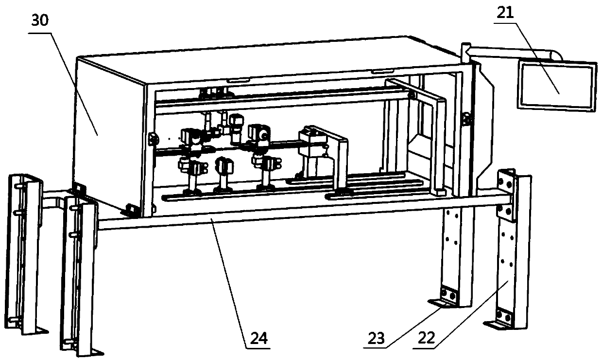
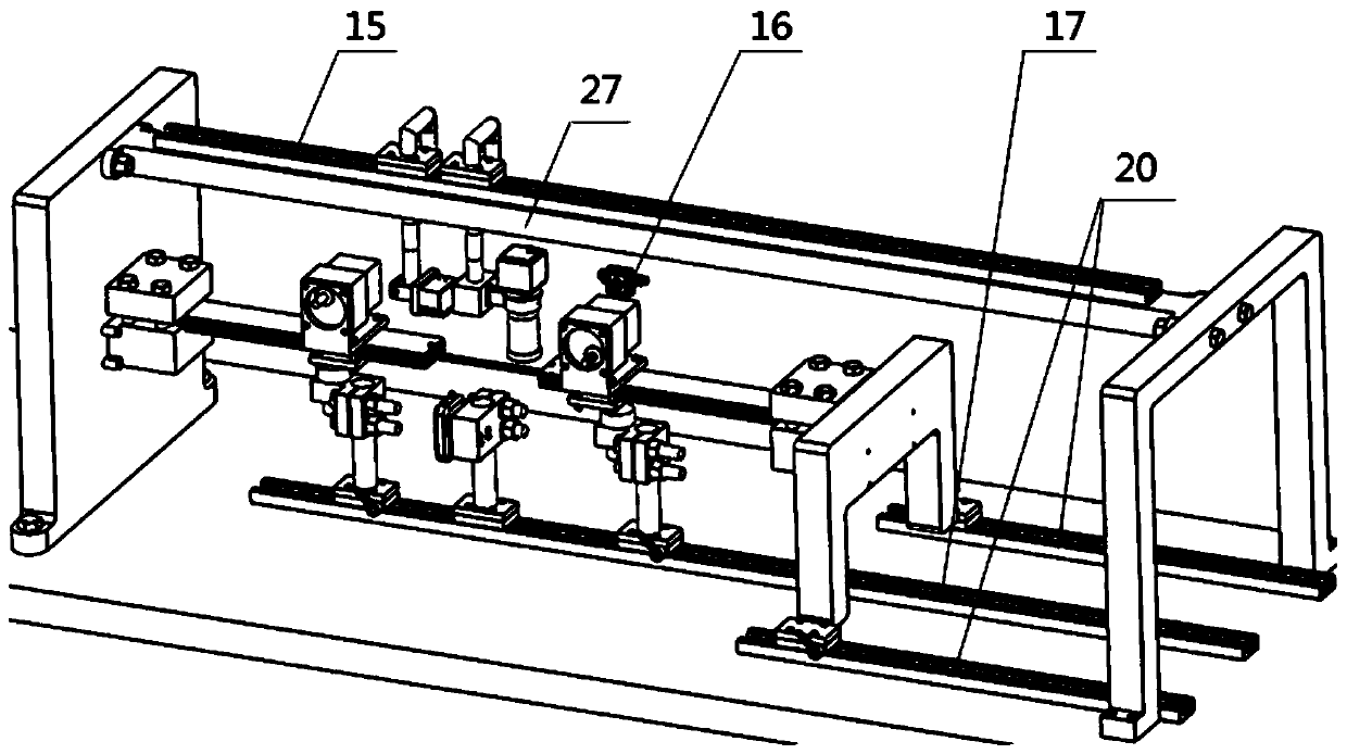
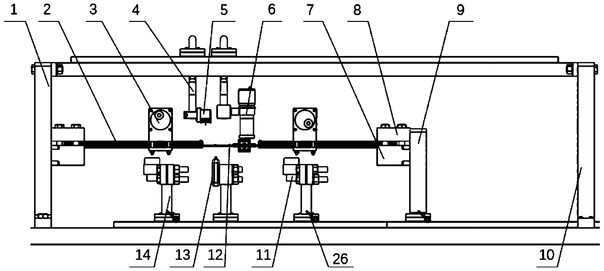
[0037] Such as Figure 1 to Figure 6 As shown, the present invention provides a composite material dynamic fatigue test device based on reverse resonance, including a double cantilever beam vibration test system, an electronic acquisition system and a measurement and control system;

[0038] The double cantilever beam vibration test system includes two cantilever vibrating beams 2, an eccentric motor 3 and a base plate 24, the left side fixed plate 1 is fixedly installed on the left side of the top of the base plate 24, and the right side fixed plate is ...


PUM


Abstract

The invention belongs to the composite material structure fatigue testing technology field and discloses a composite material dynamic fatigue testing device and method based on reverse resonance. Thetesting device comprises a double-cantilever-beam vibration testing system, an electronic acquisition system and a measurement and control system. An eccentric motor is used to drive vibration of a beam to be tested. Compared with a vibration exciter, the device has a small size and less energy consumption, and is convenient to carry. The reverse resonance of a double-cantilever vibration beam isused to drive the vibration of the beam to be tested, test efficiency is improved and energy is saved. Compared with an existing testing device, the device can be used to broaden an amplitude range ofthe beam to be tested. The eccentric motor is precisely controlled, a variety of precision instruments are used to measure and analyze a fatigue characteristic of the material to be tested from optics, acoustics, time domain waveform and other aspects, and test accuracy is extremely high. The device is simple, most of components are detachable, dismounting is convenient, portability is good and the device is easy to operate.

Description

technical field [0001] The invention belongs to the technical field of composite material structure fatigue testing, and in particular relates to a composite material dynamic fatigue testing device and method based on reverse resonance. Background technique [0002] With the deepening of research, fiber-reinforced composite materials have high specific strength, high specific modulus, good thermal stability, and certain damping and vibration reduction capabilities. Many superior properties are known. They are not only widely used in aviation Aerospace and other high-tech fields can also be used in stationery, textile machinery, medical equipment, biological engineering, building materials, chemical machinery, transportation vehicles, etc. However, composite components are often damaged or even destroyed due to stress and environmental factors during use, and fatigue damage is one of the main forms of failure. The occurrence, expansion and accumulation of fatigue damage will...

Claims


Application Information

Patent Timeline
IPC IPC(8): G01N29/04
CPCG01N3/04G01N29/04
Inventor 李晖戴哲鑫黄浩诚石有泰王俊王东升闻邦椿
Owner NORTHEASTERN UNIV
Learn More