Laser in-situ processing equipment and method based on scanning galvanometer

A scanning galvanometer and processing method technology, applied in image analysis, instruments, calculations, etc., can solve the problems of cumbersome operation process, difficult to ensure processing accuracy and efficiency, and difficult to ensure placement accuracy, so as to improve accuracy and efficiency, improve Function integration efficiency and utilization effect

Active Publication Date: 2021-07-13
XI AN JIAOTONG UNIV
View PDF0 Cites 0 Cited by
  • Summary
  • Abstract
  • Description
  • Claims
  • Application Information

AI Technical Summary

Problems solved by technology

[0003] When the traditional two-dimensional galvanometer processes a three-dimensional workpiece, it needs to adopt layering or increase the rotation axis, which is difficult to guarantee the processing accuracy and efficiency, and cannot be flexibly applied to three-dimensional laser processing, while the three-dimensional galvanometer needs to obtain the three-dimensional model of the workpiece in advance. At present, most of them use independent scanning equipment to obtain the 3D model of the object and then import it into the 3D galvanometer control software to generate the 3D processing trajectory. The operation process is cumbersome, and the workpiece needs to be placed in a specific position manually, and the placement accuracy is difficult to guarantee.

Method used


Image

  • Laser in-situ processing equipment and method based on scanning galvanometer
  • Laser in-situ processing equipment and method based on scanning galvanometer
  • Laser in-situ processing equipment and method based on scanning galvanometer

Examples


Embodiment Construction

[0033] The present invention will be further described below in conjunction with the accompanying drawings.

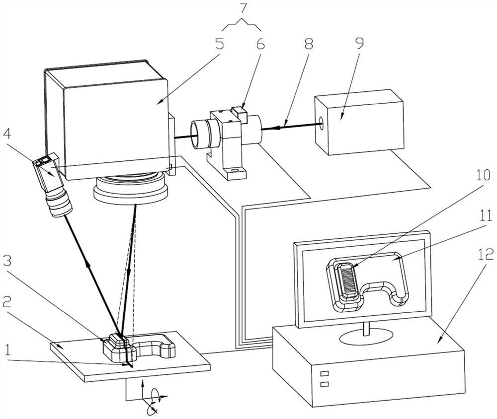
[0034] like figure 1 As shown, the laser in-situ processing equipment based on the scanning galvanometer provided by the present invention includes an industrial camera 4, a five-axis motion platform 2, a laser 9, an industrial control computer 12, and a two-dimensional galvanometer 5 and a dynamic focusing mirror 6. A three-dimensional vibrating mirror 7 is composed; wherein, the laser 9 is used to emit laser light or indicating light 8 of corresponding wavelength, which passes through the dynamic focusing mirror 6 and the two-dimensional vibrating mirror 5 in turn, and focuses on the five-axis motion platform 2; the five-axis motion platform 2 It is used to adjust the pose of the workpiece 3 on it; the industrial camera 4 is used to obtain the spot position of the laser or indicating light 8 on the five-axis motion platform 2; the industrial control computer 12 is us...


PUM


Abstract

The invention discloses a laser in-situ processing equipment and method based on a scanning galvanometer. The equipment includes an industrial camera, a five-axis motion platform, a laser, an industrial control computer, and a three-dimensional galvanometer composed of a two-dimensional galvanometer and a dynamic focusing mirror. The method includes the steps of: camera calibration, three-dimensional shape and pose measurement of the workpiece, in-situ processing path generation, three-dimensional laser in-situ processing, and processing result detection. The present invention adopts the hardware design of a three-dimensional galvanometer plus a five-axis motion platform, which fully meets the needs of the industry. The laser emits laser light or indicates light to scan the laser line on the workpiece through the three-dimensional galvanometer, and uses the principle of three-dimensional structured light to generate the three-dimensional shape of the workpiece online. Laser in-situ three-dimensional processing is performed after the in-situ processing path is generated. Therefore, the laser in-situ processing equipment and method based on the scanning galvanometer provided by the present invention realizes the integration of three-dimensional modeling, processing and detection in the laser three-dimensional processing process, and improves the positioning accuracy of the workpiece and the convenience of operation. .

Description

technical field [0001] The invention belongs to the technical field of laser processing of numerically controlled machine tools, and in particular relates to laser in-situ processing equipment and methods based on scanning galvanometers. Background technique [0002] The principle of laser processing is that the laser reaches a high energy density at the focal point after being focused by a lens, and is processed by the photothermal effect. The laser processing technology of CNC machine tools combines multi-axis machine tools, vibrating mirrors and lasers, making full use of laser non-contact processing. , high energy density and other advantages, it is used for processing including laser welding, cutting, engraving, surface modification, marking, drilling and micromachining, as well as traditional difficult-to-machine materials. [0003] When the traditional two-dimensional galvanometer processes a three-dimensional workpiece, it needs to adopt layering or increase the rota...

Claims


Application Information

Patent Timeline
Patent Type & Authority Patents(China)
IPC IPC(8): G06T7/80G06T1/00
Inventor 梅雪松李晓刘斌王晓东赵文振谢亚杰
Owner XI AN JIAOTONG UNIV
Why Eureka
Try Eureka