Eureka AIR delivers breakthrough ideas for toughest innovation challenges, trusted by R&D personnel around the world.

Magneto-rheological polishing compensation machining method and system for optical complex curved surface element and medium

A technology of magnetorheological polishing and complex curved surfaces, which is applied in the field of ultra-precision polishing, can solve problems such as changes in magnetorheological removal functions, and achieve the effects of reducing nonlinear errors, improving efficiency, and improving convergence rate

Active Publication Date: 2019-06-21
NAT UNIV OF DEFENSE TECH
View PDF6 Cites 16 Cited by
  • Summary
  • Abstract
  • Description
  • Claims
  • Application Information

AI Technical Summary

Problems solved by technology

[0005] The technical problem to be solved by the present invention: Aiming at the above-mentioned problems of the prior art, a magnetorheological polishing compensation processing method, system and medium for optical complex curved surface elements are provided. The present invention is based on the idea of ​​time compensation space to solve the curvature change of complex curved surfaces Problems leading to variations in the magnetorheological removal function enable efficient deterministic machining of optically complex curved mirrors with high surface quality

Method used


Image

  • Magneto-rheological polishing compensation machining method and system for optical complex curved surface element and medium
  • Magneto-rheological polishing compensation machining method and system for optical complex curved surface element and medium
  • Magneto-rheological polishing compensation machining method and system for optical complex curved surface element and medium

Examples


Embodiment Construction

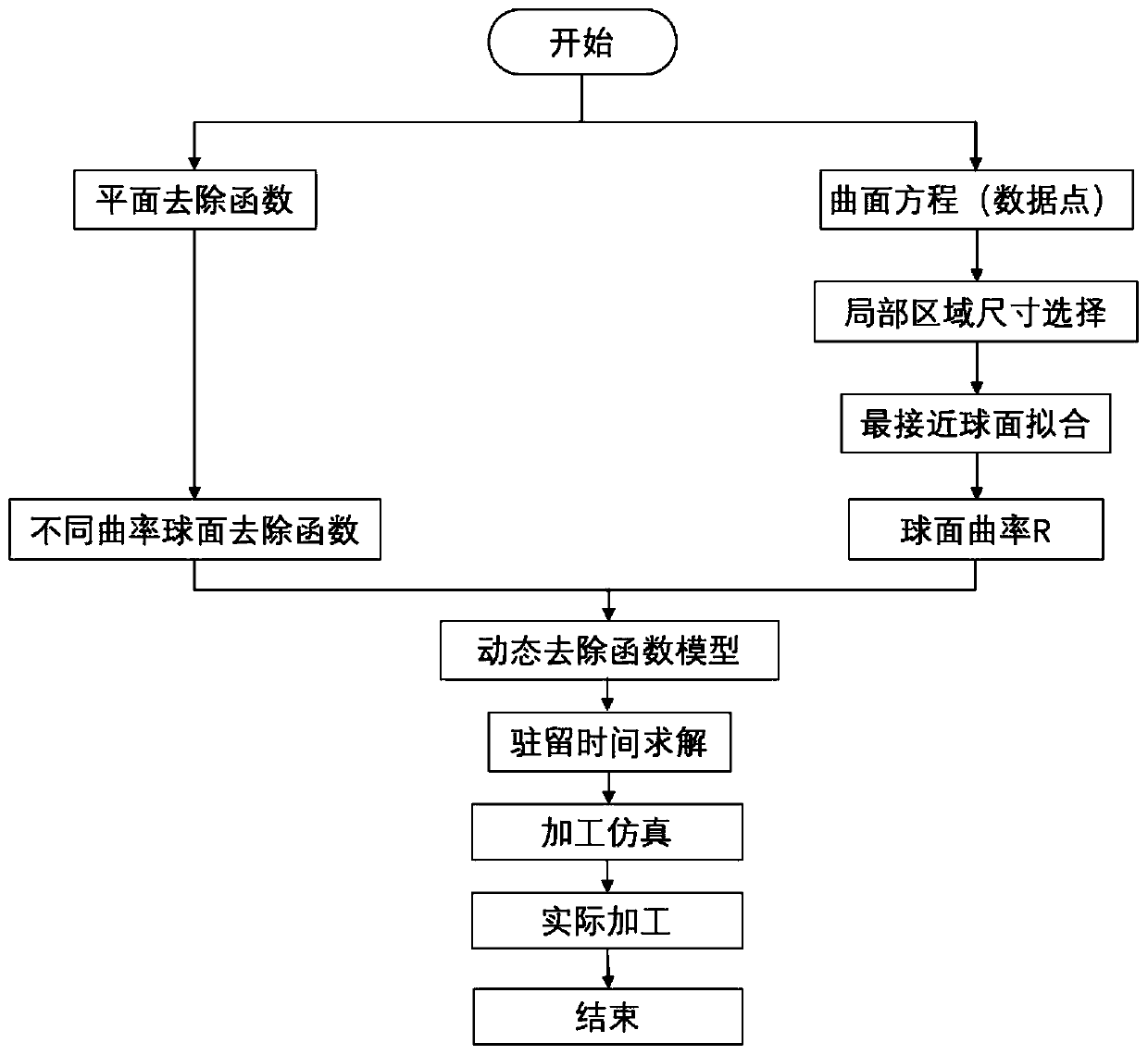
[0046] like figure 1 As shown, the implementation steps of the magnetorheological polishing compensation processing method for optical complex curved surface elements in this embodiment include:

[0047] 1) Obtain the plane removal function F for the plane workpiece of the same material as the workpiece to be processed flat ;

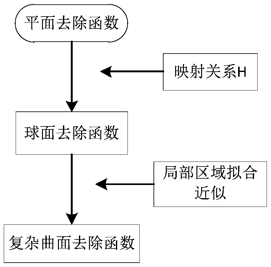
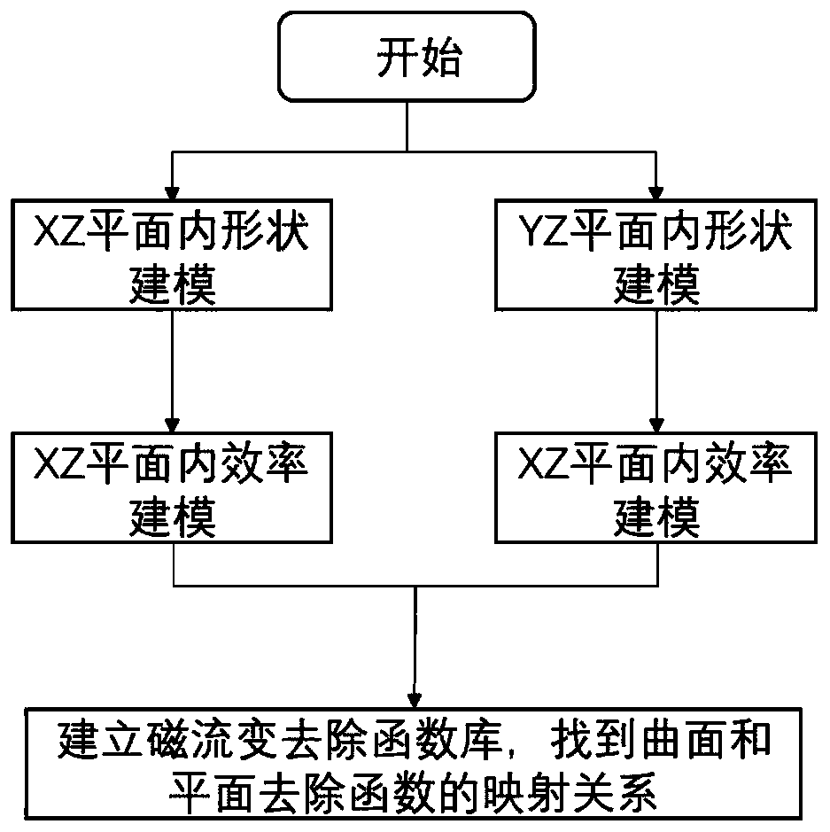
[0048] 2) Establish the mapping relationship between the spherical surface removal function and the plane removal function under the same working condition and different curvature radii for the workpiece to be processed, and according to the mapping relationship, the plane removal function F flat The spherical surface removal function F under different curvatures is obtained by mapping j-sphere ;

[0049] 3) For each dwell point in the surface area of ​​the workpiece to be processed, fit and calculate the complex surface local area S near the dwell point j-asphere The closest spherical surface S j-sphere , taking the local region S of the complex s...


PUM


Abstract

The invention discloses a magneto-rheological polishing compensation machining method and system for an optical complex curved surface element and a medium. The magneto-rheological polishing compensation machining method comprises the steps that a flat removal function is acquired; sphere removal functions under different curvatures are obtained through mapping; for each residence point in a to-be-machined workpiece surface shape area, the best fitting sphere of the complex curved surface local area nearby the residence point is calculated through fitting, and the sphere removal function corresponding to the curvature of the best fitting sphere of the complex curved surface local area is approximately taken as a removal function of the complex curved surface local area nearby the residencepoint; and a residence time solution algorithm based on a linear equation system model is built, and residence time distribution and surface shape residual errors of all the residence points are solved through simulation to guide magneto-rheological polishing of a to-be-machined workpiece. According to the magneto-rheological polishing compensation machining method and system for the optical complex curved surface element and the medium, the determinacy in the machining process can be effectively guaranteed, and the convergence rate in the machining process is increased.

Description

technical field [0001] The invention relates to the field of ultra-precision polishing of optical complex curved surface components, in particular to a magnetorheological polishing compensation processing method, system and medium for optical complex curved surface components. Background technique [0002] A complex surface is a complex, irregular, and non-revolving surface, which is generally difficult to describe accurately with mathematical equations, and is usually described by a series of discrete value points. Since there are no geometric constraints between the various value points of the complex curved surface, it will provide optical designers with a large degree of design freedom in the design, which means that optical systems containing complex curved optical elements can achieve better optical performance. [0003] Complex curved surfaces represented by free-form surfaces have rich degrees of freedom and strong phase difference correction capabilities, which can ...

Claims


Application Information

Patent Timeline
IPC IPC(8): B24B1/00B24B13/00B24B49/00G06F17/50
Inventor 彭小强胡皓戴一帆赵陶铁贵鹏石峰李信磊
Owner NAT UNIV OF DEFENSE TECH
Why Eureka
Eureka Blog
Learn More