Asymmetric micro-cavity edge emitting semiconductor laser array

A laser array, laser technology, applied in semiconductor laser devices, laser devices, structures of optical resonators, etc., to achieve the effects of good heat dissipation, easy output coupling, and consistent light output directions

Active Publication Date: 2019-06-21
CHANGCHUN UNIV OF SCI & TECH
View PDF11 Cites 2 Cited by
  • Summary
  • Abstract
  • Description
  • Claims
  • Application Information

AI Technical Summary

Problems solved by technology

However, it is difficult for this solution to ensure that the light emitting directions of each laser tube constituting the laser array are consistent in the process of stacking multiple laser arrays. The heat dissipation problem of this laser array array is more prominent; Subsequent links such as output coupling face multiple technical difficulties

Method used


Image

  • Asymmetric micro-cavity edge emitting semiconductor laser array
  • Asymmetric micro-cavity edge emitting semiconductor laser array
  • Asymmetric micro-cavity edge emitting semiconductor laser array

Examples


Embodiment 1

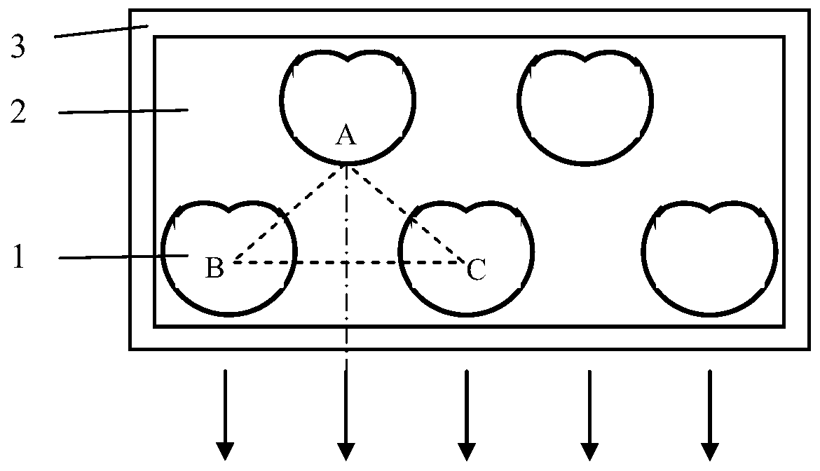
[0014] The number of single laser tubes in the front row of laser lines and the rear row of laser lines is 4, such as figure 2 As shown, the asymmetric microdisk cavity is a snail-shaped microdisk cavity, and the snail polar coordinate equation of the snail-shaped microdisk cavity is ρ(θ)=ρ 0 (1+εcosθ), where ρ(θ) is the polar diameter, ρ 0 is the characteristic radius, θ is the polar angle, ε is the deformation factor, and ρ 0 As the characteristic radius of the snail-shaped microdisk cavity, take ρ 0 = 150 μm, ε = 0.42. The distances AB and AC between the light-emitting point A of the single laser tube in the rear row of laser lines and the geometric centers B and C of the two closest laser single tubes in the front row of laser lines are equal, and the angle between AB and AC is ∠ A=120°, AB=AC=500μm, from this, it can be calculated that the geometric center distance of two adjacent laser single tubes in the front row of laser lines is about 850μm, which offsets the cha...

Embodiment 2

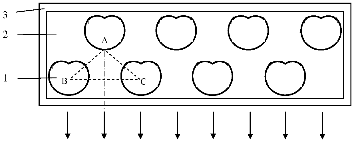
[0016] The number of single laser tubes in the front row of laser lines is 3, and the number of single laser tubes in the rear row of laser lines is 2, such as image 3 As shown, the asymmetric microdisk cavity is an elliptical microdisk cavity, the ellipse deformation factor ε is defined as the ratio of the long axis and the short axis of the ellipse, the deformation factor ε=1.2, and the length of the short axis is 120 μm. The distances AB and AC between the light-emitting point A of the single laser tube in the rear row of laser lines and the geometric centers B and C of the two closest laser single tubes in the front row of laser lines are equal, and the angle between AB and AC is ∠ A=60°, AB=AC=500μm, from this, it can be calculated that the geometric center distance of two adjacent laser single tubes in the front row of laser lines is about 500μm, which offsets the lateral radius of the two elliptical microdisk cavity cavities, The lateral radius of the cavity is also th...

Embodiment 3

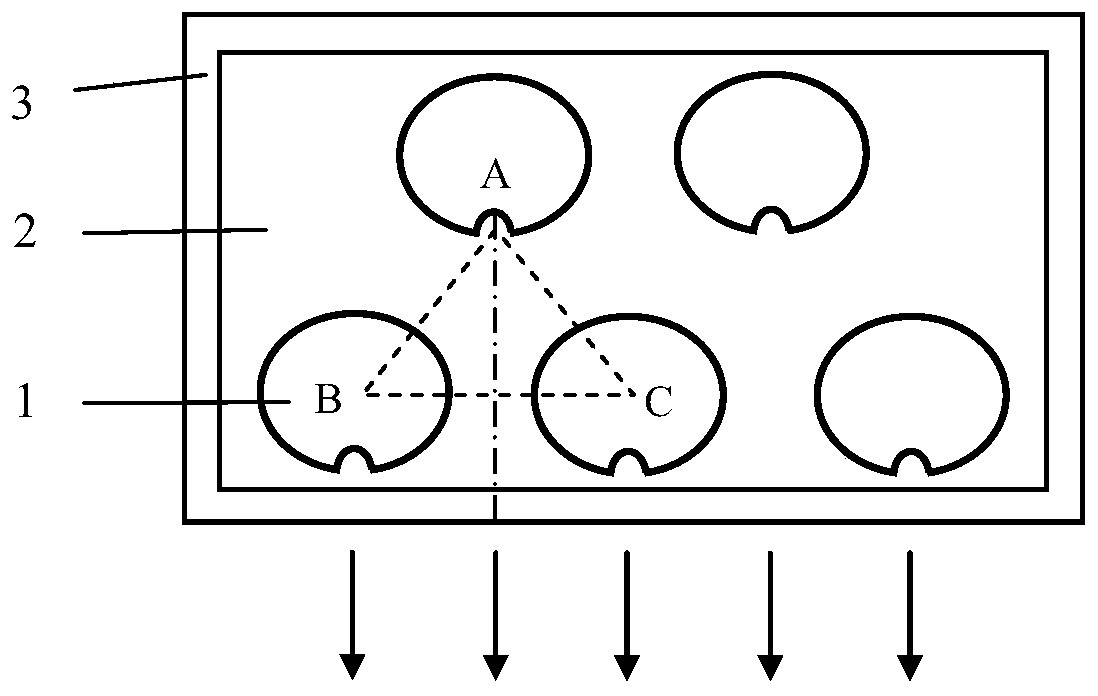
[0018] The number of single laser tubes in the front row of laser lines is 3, and the number of single laser tubes in the rear row of laser lines is 2, such as Figure 4 As shown, the asymmetric microdisk cavity is a helical microdisk cavity, and the helical polar coordinate equation of the helical microdisk cavity is where ρ(θ) is the polar diameter, ρ 0 is the characteristic radius, θ is the polar angle, ε is the deformation factor, and ρ 0 As the characteristic radius of the helical microdisk cavity, take ρ 0= 200 μm, ε = 0.1. The distances AB and AC between the light emitting point A of the single laser tube in the rear row of laser lines and the geometric centers B and C of the two closest laser single tubes in the front row of laser lines are equal, and the angle between AB and AC is ∠ A=90°, AB=AC=900μm, from this, it can be calculated that the geometric center distance of two adjacent laser single tubes in the front row of laser lines is about 1270μm, which offsets...


PUM


Abstract

The invention discloses an asymmetric micro-cavity edge emitting semiconductor laser array, and belongs to the technical field of semiconductor lasers. An existing semiconductor laser stack array faces multiple technical problems in beam shaping and output coupling. According to the asymmetric micro-cavity edge emitting semiconductor laser array, laser single tubes forming the laser array are asymmetric micro-cavity edge emitting semiconductor lasers; a front row of laser linear arrays and a back row of laser linear arrays are located on the same substrate; in the front row of the laser lineararrays, the 3-4 laser single tubes are linearly arranged according to the same geometric center distance; in the back row of the laser linear arrays, the 2-4 laser single tubes are linearly arrangedaccording to the same geometric center distance; the geometric center distance of each laser single tube in the front row of the laser linear arrays is the same as the geometric center distance of each laser single tube in the back row of the laser linear arrays; the laser single tubes are same in light-emitting direction, and are forward; and an optical axis of light emitted by each laser singletube in the back row of the laser linear arrays is away from the geometric center of the closest laser single tube in the front row of the laser linear arrays for 1/2 of the geometric center distance.

Description

technical field [0001] The invention relates to an asymmetric micro-disk cavity edge-emitting semiconductor laser array, which utilizes spiral, elliptical and helical asymmetric micro-disk cavities to form an array in the form of interstitial arrangement, greatly improving the output optical power of a semiconductor laser light source, and belongs to semiconductor The field of laser technology. Background technique [0002] Microdisk cavity edge-emitting semiconductor lasers have the characteristics of low threshold, small size, simple geometry, dynamic mode operation, and easy integration with other electronic components. However, it cannot meet the output optical power requirements of semiconductor laser light sources in the fields of all-optical networks and optoelectronic information, because the output optical power of microdisk cavity edge-emitting semiconductor lasers is lower than that of ordinary semiconductor lasers. Increasing the size of the laser to expand the ...

Claims


Application Information

Patent Timeline
Patent Type & Authority Applications(China)
IPC IPC(8): H01S5/40H01S5/10
Inventor 晏长岭杨静航刘云冯源郝永芹逢超
Owner CHANGCHUN UNIV OF SCI & TECH
Why Eureka
Try Eureka