Three-turn-one-shift decoupling ankle joint rehabilitation robot

A rehabilitation robot and joint technology, applied in passive exercise equipment, physical therapy, etc., can solve the problems of inconvenient control, coupling inconvenient control, etc., and achieve the effect of convenient mechanism installation, saving production cost and time, and simple motion pairs

Active Publication Date: 2019-06-25
YANSHAN UNIV
View PDF17 Cites 6 Cited by
  • Summary
  • Abstract
  • Description
  • Claims
  • Application Information

AI Technical Summary

Problems solved by technology

The above-mentioned robot and workbench can perform dorsiflexion, plantarflexion, varus, valgus, internal rotation, and external rotation training on the ankle joint, but the mechanism has coupling in kinematics and is inconvenient to control; the public number is CN201510472613.X The patent discloses a parallel ankle joint rehabilitation robot and its control method. The mechanism includes a base on which a support frame is inserted, and an adjustment mechanism is mounted on a movable card on the support frame. The adjustment mechanism includes a main rod, Forearm rod and leg support rod, the front end of the main rod is connected with the forearm rod, the leg support rod is installed and connected with the main rod, the forearm rod is equipped with a connecting rod, the main rod and the support frame are movable and clamped; it also includes the adjustment mechanism and the movement The mechanism adopts pneumatic muscle or linear motor as the driver, the front end of the driving mechanism is connected to the connecting rod in the adjustment mechanism, the end of the driving mechanism is connected to the movement mechanism, and the movement mechanism is mounted on the rear end of the main rod.
The robot disclosed in the invention can adjust the range of motion to adapt to the use of different patients, and can cover the three degrees of freedom of the ankle joint for exercise training, but it is not easy to control

Method used


Image

  • Three-turn-one-shift decoupling ankle joint rehabilitation robot
  • Three-turn-one-shift decoupling ankle joint rehabilitation robot
  • Three-turn-one-shift decoupling ankle joint rehabilitation robot

Examples


Embodiment Construction

[0028] Exemplary embodiments, features, and performance aspects of the present invention will be described in detail below with reference to the accompanying drawings. The same reference numbers in the figures indicate functionally identical or similar elements. While various aspects of the embodiments are shown in drawings, the drawings are not necessarily drawn to scale unless specifically indicated.

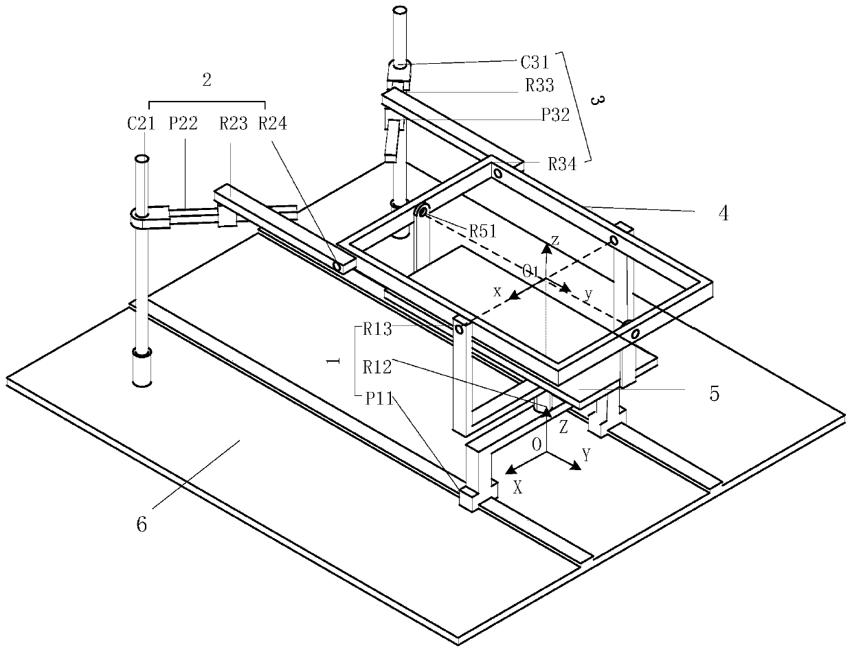
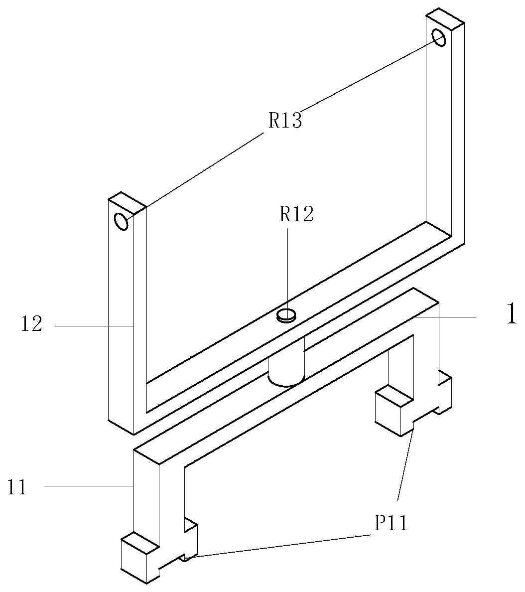
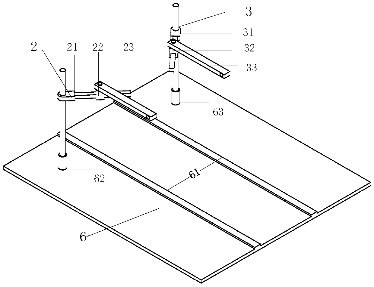
[0029] exist figure 1 In the schematic diagram of the overall structure of the robot shown, the fuselage is composed of a symmetrical hybrid mechanism, including a base 6, a moving platform 4, three branches 1, 2, 3 connecting the base 6 and the moving platform 4, and the moving platform 4 connected in series. The pedal 5 on the top; the parallel part of the hybrid mechanism is a 2-CPRR-PRR parallel mechanism, where C represents a cylindrical pair, P represents a moving pair, and R represents a rotating pair, and the cylindrical pair is a moving pair and a rotating pair The ...


PUM


Abstract

The invention relates to a three-turn-one-shift decoupling ankle rehabilitation robot which comprises a machine body, a driving mechanism and a monitoring system. The machine body consists of a symmetrical series-parallel mechanism and comprises a base, a movable platform, a foot pedal and three branches for connecting the base and the movable platform, preferably, the first branch of the three branches is a PRR branch, the second branch and the third branch are CPRR branches and are symmetrically distributed relative to the bottom of the base; the pedal and the movable platform are connectedin series to form a local branch, and the whole mechanism is a 3R1T mechanism; preferably, the mechanism contained in the robot is a decoupling mechanism in kinematics, and can independently achieve dorsiflexion / phalangeal flexion, varus / valgus and pronation / supination in ankle joint movement by controlling different branches. The three-turn-one-shift decoupling ankle rehabilitation robot has a wide application range, can be used not only for ankle rehabilitation training, but also for implanting corresponding massage components on the pedals, and can also be used for family health care.

Description

technical field [0001] The invention belongs to the field of ankle joint rehabilitation, in particular to a symmetrical decoupling ankle joint rehabilitation robot capable of realizing three rotations and one transfer. Background technique [0002] Ankle joint injury is a common bone joint injury. The micro-adjustment hub of the human body's walking gait and balance lies in the ankle joint. Rehabilitation training for the ankle joint is of great significance to patients. Many patients with stroke and hemiplegia also urgently need to strengthen the training of the ankle joint. In order to reduce the workload of medical staff and improve the training effect, ankle joint rehabilitation training is carried out with training devices. In the prior art, most of the training devices use series mechanisms to realize the movement of the workbench, but the structural strength is often poor and the degree of freedom of movement is small; while the training devices using parallel mechani...

Claims


Application Information

Patent Timeline
Patent Type & Authority Applications(China)
IPC IPC(8): A61H1/02
Inventor 曾达幸吴华芳荣令魁周建华孙水余
Owner YANSHAN UNIV
Why Eureka
Try Eureka