Exhibit microenvironment monitoring system

A monitoring system and micro-environment technology, applied in the circuit field, can solve problems such as faults, data signal errors, and signal frequency hopping in the micro-environment monitoring system of exhibits

Active Publication Date: 2019-06-25
王琪
View PDF5 Cites 12 Cited by
  • Summary
  • Abstract
  • Description
  • Claims
  • Application Information

AI Technical Summary

Problems solved by technology

[0002] The network video monitoring system is a system that combines computer IP video technology, video and audio data compression and decompression processing technology, and Internet application technology. The remote video control system can release the monitoring information monitoring center and make it reachable through the computer network. Desktop computer, so as to integrate with information ma

Method used


Image

  • Exhibit microenvironment monitoring system
  • Exhibit microenvironment monitoring system

Examples


Embodiment 1

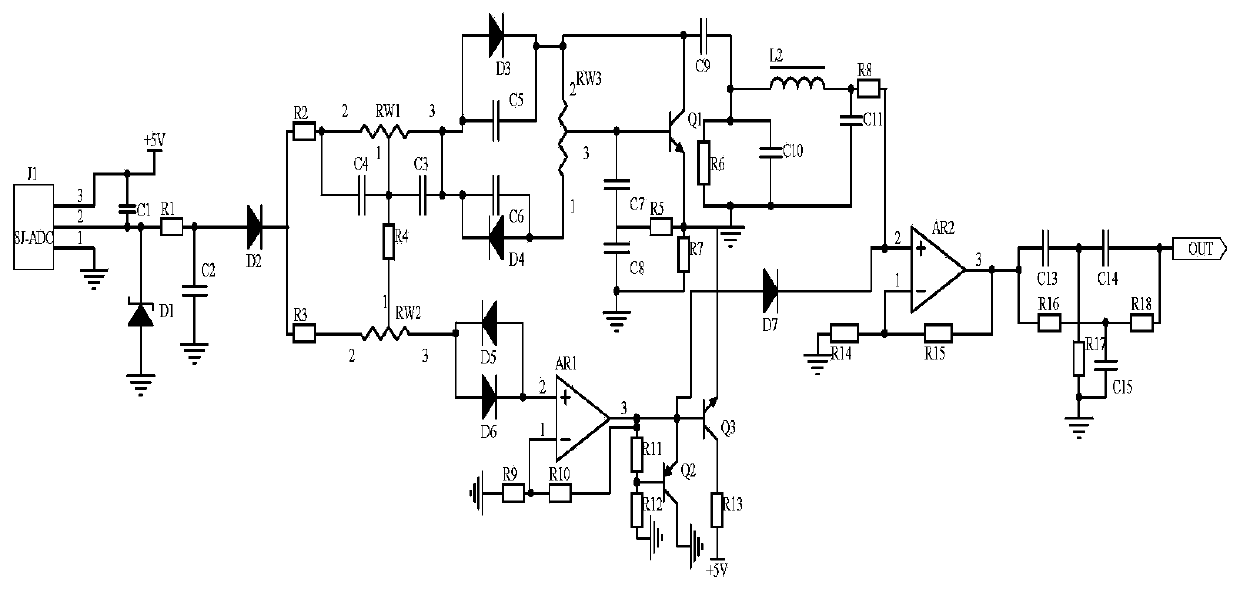
[0012] Embodiment 1, an exhibit micro-environment monitoring system includes a frequency acquisition circuit, a separation calibration circuit and a frequency selection output circuit, the frequency acquisition circuit collects the analog signal at the input end of the signal transmission channel in the control terminal of the exhibit micro-environment monitoring system, the signal is The transmission channel is the channel through which the control terminal of the exhibit's micro-environment monitoring system receives analog signals. The separate calibration circuit uses variable resistor RW1, variable resistor RW2, capacitor C3, and capacitor C4 to divide the output signal of the frequency acquisition circuit into two signals. Use diode D3, diode D4, capacitor C5, capacitor C6 and variable resistor RW3 to form a rectifier circuit to rectify the signal, and use transistor Q1 and capacitor C7-capacitor C9 to form a frequency modulation circuit to tune the frequency of the signal...

Embodiment 2

[0015] Embodiment 2, on the basis of Embodiment 1, the frequency selection output circuit uses the resistor R19-resistor R21 and the capacitor C13-capacitor C15 to form a frequency selection circuit to screen out the signal output of a single frequency, and the signal of a single frequency is relatively stable. It can filter out abnormal signals, that is, it is the compensation signal for the analog signal at the input end of the signal transmission channel in the control terminal of the exhibit's micro-environment monitoring system. The other end of the resistor R17 is connected to one end of the resistor R17 and the capacitor C14, the other end of the capacitor C14 is connected to one end of the resistor R18 and the signal output port, the other end of the resistor R16 is connected to one end of the capacitor C15 and the other end of the resistor R18. The other end is grounded.

Embodiment 3

[0016] Embodiment 3, on the basis of Embodiment 2, the frequency acquisition circuit selects the signal frequency collector J1 of the model SJ-ADC to collect the analog signal at the input end of the signal transmission channel in the control terminal of the microenvironment monitoring system of the exhibit, and the voltage regulator tube D1 Voltage stabilization, the power terminal of the signal frequency collector J1 is connected to one end of the capacitor C1 and the power supply +5V, the ground terminal of the signal frequency collector J1 is grounded, and the output terminal of the signal frequency collector J1 is connected to the other end of the capacitor C1 and one end of the resistor R1 , The cathode of the Zener tube D1, the anode of the Zener tube D1 is grounded, the other end of the resistor R1 is connected to one end of the capacitor C2 and the anode of the diode D2, the other end of the capacitor C2 is grounded, and the cathode of the diode D2 is connected to the o...


PUM


Abstract

The present invention discloses an exhibit microenvironment monitoring system. The system comprises a frequency collection circuit, a separation calibration circuit and a frequency selection output circuit. The frequency collection circuit is configured to collect simulation signals of an input end of a signal transmission channel in a control terminal of the exhibit microenvironment monitoring system, the separation calibration circuit utilizes a variable resistor RW1, a variable resistor RW2, a capacitor C3 and a capacitor C4 to divide the output signals of the frequency collection circuit into two paths of signals, the frequency selection output circuit utilizes resistors R19-R21 and capacitors C13-C15 to form a frequency selection circuit to screen out signals with a single frequency for output so as to achieve real-time detection of the signal condition of the signal transmission channel in the control terminal in the exhibit microenvironment monitoring system and convert the signal frequencies to the compensation signals of the simulation signals of the input end of the signal transmission channel in the exhibit microenvironment monitoring system.

Description

technical field [0001] The invention relates to the technical field of circuits, in particular to an exhibit microenvironment monitoring system. Background technique [0002] The network video monitoring system is a system that integrates computer IP video technology, video and audio data compression and decompression processing technology, and Internet application technology. The remote video control system can release the monitoring information monitoring center and make it accessible through the computer network. On the desktop computer, it is integrated with the information management system and the office automation system to better serve the management and improve the management level and efficiency. Management level and efficiency, however, the micro-environment monitoring system of the exhibits sometimes fails, especially the frequency hopping and distortion of the signal, which leads to signal disorder and errors in the data signal of the micro-environment monitorin...

Claims


Application Information

Patent Timeline
IPC IPC(8): G05B19/042
Inventor 王琪
Owner 王琪
Why Eureka
Try Eureka