High-precision three-dimensional point cloud map construction method based on low-cost equipment

A 3D point cloud and map construction technology, applied in 3D modeling, image analysis, image data processing, etc., can solve the problems of high cost, difficult equipment maintenance, and large one-time investment, so as to achieve high cost and save map building cost effect

Active Publication Date: 2019-06-25
AUTOCORE INTELLIGENT TECH NANJING CO LTD
5 Cites 25 Cited by

AI-Extracted Technical Summary

Problems solved by technology

High cost, large one-time investment, and difficult equipment maintenance are the main problems fa...

Abstract

The invention aims at an automatic driving scene, and provides a high-precision three-dimensional point cloud map construction method based on low-cost equipment, and the method comprises the steps: sequentially carrying out the five steps: point cloud preprocessing, inter-frame registration, key frame screening, gps and imu data fusion and key frame pose optimization construction on a low-cost three-dimensional point cloud map construction platform, and generating a three-dimensional point cloud map. The platform is composed of a laser point cloud acquisition unit, an imu data acquisition unit, a gps data acquisition unit and a computing platform, wherein the laser point cloud acquisition unit adopts a 16-line or 32-line laser radar. The gps data acquisition unit adopts low-cost gps withan error level of meter and provides low-frequency latitude and longitude information for the system. And the imu data acquisition unit provides high-frequency acceleration and angular velocity information for the system. According to the method, low-cost mapping equipment is used in cooperation with a brand new mapping algorithm, and the construction cost of the three-dimensional point cloud mapis saved on the premise that the same precision is met.

Application Domain

Technology Topic

Angular velocityGps data +13

Image

  • High-precision three-dimensional point cloud map construction method based on low-cost equipment
  • High-precision three-dimensional point cloud map construction method based on low-cost equipment
  • High-precision three-dimensional point cloud map construction method based on low-cost equipment

Examples

  • Experimental program(1)
  • Effect test(1)

Example Embodiment

[0025] Examples:
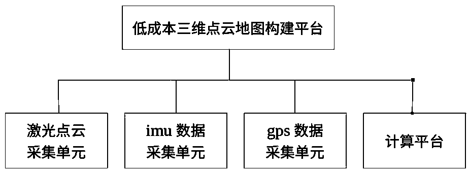
[0026] Such as figure 1 As shown, this embodiment provides a low-cost laser point cloud hardware combination solution for autonomous driving scene map construction, using low-cost satellite navigation signal receiving equipment (error level: meters), IMU (inertial measurement unit) and low cost Lidar (16 lines, 32 lines). The hardware system consists of four parts: laser point cloud acquisition unit, imu data acquisition unit, gps data acquisition unit, and computing platform.
[0027] 1> The laser point cloud acquisition unit uses a 32-line lidar to collect 3D point cloud data at a frequency of 10 Hz. This unit provides the system with accurate point cloud data with time stamps, and is the most important part of the entire system.
[0028] 2> The imu data acquisition unit uses a thousand-yuan low-cost imu, and the program completes the zero drift correction and temperature compensation after power-on. This unit provides the system with high-frequency (50Hz) acceleration and angular velocity information, and obtains the lidar motion trajectory and attitude with time stamps through ekf fusion gps data.
[0029] 3> The GPS data acquisition unit uses a thousand-yuan low-cost GPS, an error level meter, and a data output frequency of 4Hz. This unit provides low-frequency latitude and longitude information for the system, and high-frequency (50Hz) lidar trajectory and attitude data with time stamps can be obtained through ekf fusion with high-frequency imu data.
[0030] 4> The computing platform uses a dell notebook (i7-8750h processor, 16G memory), the operating system is ubuntu16.04, and the map generation software is based on the PCL point cloud processing library, the map optimization tool library and ROS.
[0031] Such as figure 2 As shown, in conjunction with the aforementioned low-cost laser point cloud map mapping hardware solution, and the laser point cloud map generation algorithm form a set of offline mapping solutions. The algorithm first preprocesses the point cloud, then uses the preprocessed point cloud to stitch the local map, and then uses the geographic trajectory fused by the navigation signal and the IMU to correct the key frames in the local map, and finally optimizes the result with the key frame as the constraint A three-dimensional point cloud map conforming to the geographic trajectory.
[0032] The software process of constructing a 3D point cloud mainly includes five parts: point cloud preprocessing, inter-frame registration, key-frame screening, gps and imu data fusion, and key-frame pose optimization. among them:
[0033] 1> Point cloud preprocessing: first mark the ground points and non-ground points in the current point cloud frame, then mark the corner points and plane points in the non-ground points, and eliminate the point cloud data except for ground points, corner points and plane points. All points outside.
[0034] 2> Inter-frame registration: use the pre-processed current point cloud frame and the pre-processed previous point cloud to perform point cloud registration, and calculate the displacement of the lidar from the point cloud data of the previous frame to this frame of point cloud data Matrix and posture rotation matrix, starting from the point cloud data of the first frame received by the system, use the displacement matrix and rotation matrix of adjacent frames to accumulate adjacent point cloud frames to obtain a continuous point cloud map.
[0035] 3> Filter key frame: take the first frame of point cloud data received by the system as the first key frame. As the inter-frame registration progresses, the Euclidean distance from the current frame to the previous key frame is counted. When the Euclidean distance is greater than the set When the threshold is set, the current frame is marked as a key frame.
[0036] 4> GPS and imu data fusion: First, use the acceleration and angular velocity of imu to calculate the time-stamped path points, and use the ekf method to fuse the GPS path points and the path points integrated by the imu to obtain the fused path point data set.
[0037] 5> Key frame pose optimization: according to the time stamp of the path point in 4> Find the two path points closest to the current point cloud key frame in the obtained fusion path point data set. Under the assumption of uniform linear motion, linear interpolation is used to calculate the assumed pose of the key frame based on the path point. Assuming that the pose is the goal of convergence, optimize the displacement matrix and rotation matrix of each frame from the previous key frame to the current key frame.
[0038] The pseudo code of the process is as follows:
[0039] BEGIN
[0040] IF point cloud data arrives in THEN
[0041] a. Perform point cloud preprocessing
[0042] b. Inter-frame registration
[0043] c. According to the result of inter-frame registration, stitch the current frame into the point cloud map
[0044] IF The Euclidean distance between the current frame and the previous key frame reaches the threshold THEN
[0045] Add the current point cloud to the key frame sequence
[0046] IF Find the two path points before and after the time stamp closest to the current key frame THEN
[0047] Use the two path points before and after to get the hypothetical pose matrix to optimize the previous
[0048] Key frames up to the current key frame and the displacement matrix of each frame
[0049] Rotation matrix
[0050] END IF
[0051] END IF
[0052] END IF
[0053] END

PUM

no PUM

Description & Claims & Application Information

We can also present the details of the Description, Claims and Application information to help users get a comprehensive understanding of the technical details of the patent, such as background art, summary of invention, brief description of drawings, description of embodiments, and other original content. On the other hand, users can also determine the specific scope of protection of the technology through the list of claims; as well as understand the changes in the life cycle of the technology with the presentation of the patent timeline. Login to view more.

Similar technology patents

Classification and recommendation of technical efficacy words

Why Eureka
Try Eureka