Automatic polish-grinding system and automatic polish-grinding process for thin-wall stamping part

A stamping, thin-walled technology, used in manufacturing tools, other manufacturing equipment/tools, manipulators, etc., can solve the problem of inability to completely remove surface flaws or defects on the workpiece, unfavorable high efficiency, high-quality production, and inability to ensure grinding pressure. and other problems, to improve the grinding and polishing effect, improve production efficiency and product quality, and solve the effect of poor surface quality

Active Publication Date: 2019-06-28
WUHAN UNIV OF TECH
View PDF6 Cites 8 Cited by
  • Summary
  • Abstract
  • Description
  • Claims
  • Application Information

AI Technical Summary

Problems solved by technology

[0003] In addition, in the traditional manual grinding process, the grinding pressure of the abrasive tool and the workpiece is manually adjusted and controlled, which does not ensure that the grinding pressure is appropriate. It also requires the adjustment personnel to have rich experience, and when changing different workpieces , it needs to be adjusted again, which is not conducive to high-efficiency and high-quality production
In the process of grinding and polishing, if the grinding pressure is too small, the flaws or defects on the surface of the workpiece cannot be completely removed; if the grinding pressure is too high, it will easily lead to excessive grinding, causing damage to the workpiece and the abrasive tool, so the gap between the abrasive tool and the workpiece The grinding pressure between them is the key to the grinding and polishing process

Method used


Image

  • Automatic polish-grinding system and automatic polish-grinding process for thin-wall stamping part
  • Automatic polish-grinding system and automatic polish-grinding process for thin-wall stamping part
  • Automatic polish-grinding system and automatic polish-grinding process for thin-wall stamping part

Examples


Embodiment Construction

[0043] In order to better understand the patent of the present invention, the following describes the patent of the present invention with reference to the drawings and specific embodiments.

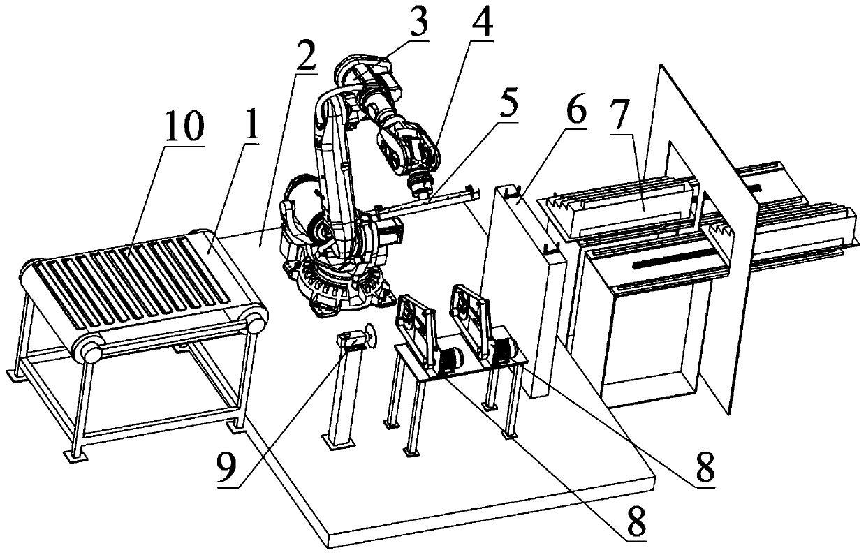
[0044] Such as figure 1 Shown is a schematic diagram of the overall structure of the automatic grinding and polishing system of the present invention, including conveyor belt 1, base 2, industrial robot 3, force control sensor 4, pneumatic clamp 5, lock seat 6, automatic feeding device 7, sanding belt machine 8, and Slicer 9. The industrial robot 3 is installed on the mounting base 2. The six-axis end of the industrial robot 3 is equipped with a force control sensor 4, and a pneumatic clamp 5 is installed under the force control sensor 4; the motor of the slicer 9 is equipped with a saw blade and two sand The belt conveyor 8 is respectively equipped with a narrow belt with coarse sand and a wide belt with fine sand. The automatic feeding device 7 and the conveyor belt 1 are respectively arr...


PUM


Abstract

The invention provides an automatic polish-grinding system and an automatic polish-grinding process for a thin-wall stamping part. The automatic polish-grinding system mainly comprises a mounting base, a six-axis robot, a pneumatic clamp, a force control sensor, a slicer, a belt sander, a lock seat, an automatic feeding device, a conveying belt and the like, wherein the force control sensor and the pneumatic clamp are arranged on a flange plate at the tail end of the six-axis robot; the slicer, the belt sander and the lock seat are all arranged on the base through a mounting seat; and the automatic feeding device and the conveying belt are respectively arranged on two sides of the base. After a workpiece is grabbed from the automatic feeding device by the pneumatic clamp for an industrialrobot, the workpiece is sequentially machined by the slicer and the belt sander, and then is discharged by the conveying belt. According to the automatic polish-grinding system, the automatic grindingand polishing of the thin-wall stamping part is achieved, the efficiency and the quality of grinding and polishing are higher than those of manual grinding and polishing, and meanwhile, the use of manpower in grinding and polishing is reduced, so that the automatic polish-grinding system has broad application prospects in thin-wall stamping part machining, and is able to improve production efficiency to bring considerable benefits for enterprises.

Description

Technical field [0001] The invention belongs to the field of mechanical processing, and relates to a grinding and polishing system, in particular to an automatic grinding and polishing system and an automatic polishing process for thin-walled stamping parts. Background technique [0002] In industrial applications, after many thin-walled stamping parts are formed by stamping, excess material will remain at both ends, which need to be cut to meet the size requirements; at the same time, the surface roughness of the stamping parts does not meet the requirements and needs to be processed. polishing. At present, manual grinding and polishing are mostly used in actual production, but the traditional manual processing methods have many shortcomings, such as: (1) the harm of dust environment to the human body; (2) rising labor cost; (3) relying on personal experience and quality. Guarantee etc. Therefore, the grinding and polishing process must be fully automated and unmanned. [0003]...

Claims


Application Information

Patent Timeline
Patent Type & Authority Applications(China)
IPC IPC(8): B23P23/04B23P15/00B25J11/00
Inventor 吴超群汪俊鹏
Owner WUHAN UNIV OF TECH
Why Eureka
Try Eureka