Device with electrostatic protection structure and preparation method thereof
A technology of electrostatic protection and conductive structure, applied in the direction of circuits, electrical components, electric solid devices, etc., can solve the problems of OLED devices without bright spots, device damage, and no bright spots, so as to reduce electrostatic effects, prolong service life, and solve device damage Effect
- Summary
- Abstract
- Description
- Claims
- Application Information
AI Technical Summary
Problems solved by technology
Method used
Image
Examples
Embodiment 1
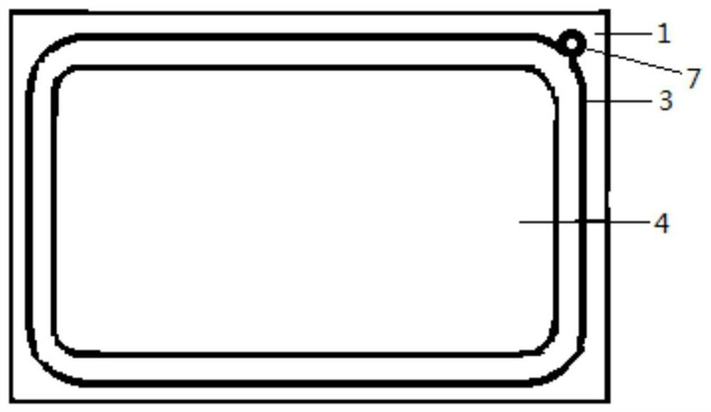
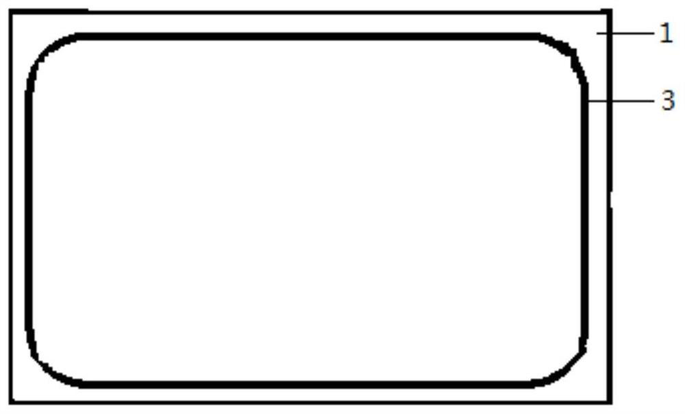
[0036]Such asfigure 1 A schematic structural diagram of a device having an electrostatic protective structure of the present embodiment includes, a substrate 1, a cover plate, and a light emitting assembly 4 disposed between the substrate and the cover plate, the substrate 1 having an edge The conductive structure 3 provided in the periphery is continuously disposed and surrounded by the light emitting assembly 1 to form a closed cyclic structure; a grounded ITO (indium tin oxide) wire coupled to the substrate circuit connection with a substrate circuit 7 to export static electricity. Among them, ifimage 3 As shown, the conductive structure 3 includes a substrate groove provided on a substrate and an anti-static filler filled in the substrate groove. In this embodiment, the antistatic filler is TiO2, SnO can also be used in other embodiments2, In2O3Such as conductive substances, only can play a conductive role.
[0037]The preparation method of the device with the anti-static structure...
Embodiment 2
[0040]The device with an electrostatic protection structure of this embodiment includes a substrate, a cover plate, and a light-emitting assembly arranged between the substrate and the cover plate. The substrate has a conductive structure arranged along its periphery, and the conductive structure is continuous. The light emitting component is arranged and surrounded to form a closed ring structure; one place of the closed ring structure is connected to a grounded ITO wire connected with the circuit of the substrate to discharge static electricity. Wherein, the conductive structure 3 includes a substrate groove provided on the substrate and an antistatic filler filled in the substrate groove, and also includes a cover plate groove provided on the cover plate and a cover plate recess filled in the cover plate. The anti-static filler in the groove, the substrate groove and the cover plate groove are arranged opposite to each other, forming a closed space for filling the anti-static fil...
Embodiment 3
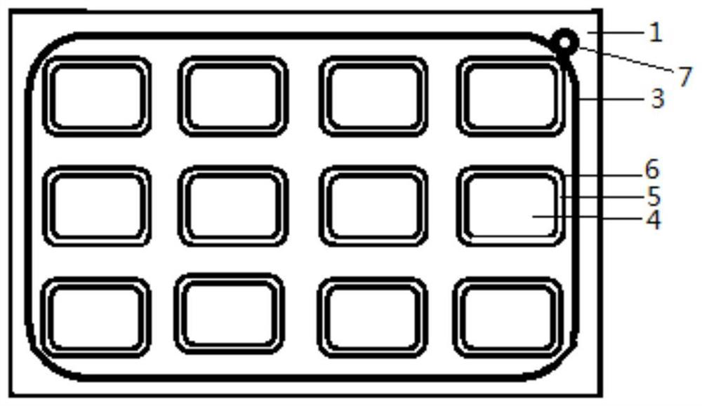
[0044]Such asfigure 2 Shown here is a schematic structural view of the device with an electrostatic protection structure of this embodiment, which includes a substrate 1, a cover plate, and a plurality of light-emitting components 4 arranged between the substrate and the cover plate. The substrate 1 has an edge A conductive structure 3 is arranged on the periphery thereof, and the conductive structure is continuously arranged and surrounds all the light-emitting components 4 to form a closed ring structure; one place of the closed ring structure is connected to a grounded ITO wire 7 connected to the substrate circuit. Wherein, the conductive structure 3 includes a substrate groove provided on the substrate and an antistatic filler filled in the substrate groove, and also includes a cover plate groove provided on the cover plate and a cover plate recess filled in the cover plate. The anti-static filler in the groove, the substrate groove and the cover plate groove are arranged opposi...
PUM
 Abstract
Description
Claims
Application Information
 - R&D
- Intellectual Property
- Life Sciences
- Materials
- Tech Scout
- Unparalleled Data Quality
- Higher Quality Content
- 60% Fewer Hallucinations
Browse by: Latest US Patents, China's latest patents, Technical Efficacy Thesaurus, Application Domain, Technology Topic, Popular Technical Reports.
© 2025 PatSnap. All rights reserved.Legal|Privacy policy|Modern Slavery Act Transparency Statement|Sitemap|About US| Contact US: help@patsnap.com


