

Glass thinning and coating method and equipment
A glass thinning and coating equipment technology, applied in sputtering coating, ion implantation coating, vacuum evaporation coating and other directions, can solve the problem of fixture dislocation, spanning two fixtures, easy to break, etc., to achieve stable and accurate Positioning, good resistance uniformity, good coating effect
- Summary
- Abstract
- Description
- Claims
- Application Information
AI Technical Summary
Problems solved by technology
Method used
Image

Examples
Embodiment approach
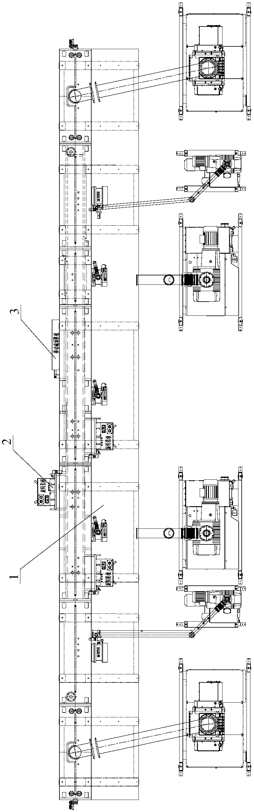
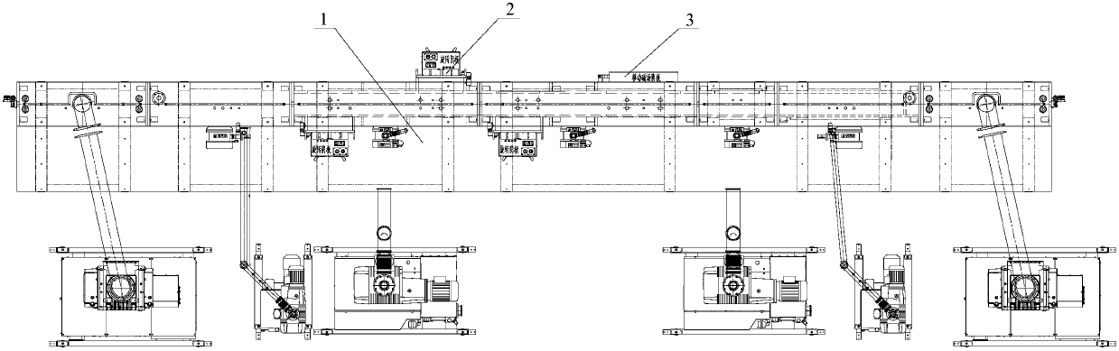
[0035] figure 1 It shows an embodiment of the glass thinning and coating equipment of the present invention, which sequentially includes an inlet chamber, an inlet buffer chamber, an inlet transfer chamber, a process chamber, an outlet transfer chamber, an outlet buffer chamber and an outlet chamber, and the process chamber includes a plurality of magnetrons The sputtering chamber, the magnetron sputtering chamber 1 is equipped with a rotating cathode 2, and the rotating cathodes 2 of multiple magnetron sputtering chambers 1 are not all located on the same side; the production line also includes a transmission system, and the transmission system includes a magnetic guide friction transmission device.
[0036] The glass thinning and coating equipment for the coating method of claim 1 in this embodiment comprises an inlet chamber, an inlet buffer chamber, an inlet transfer chamber, a process chamber, an outlet transfer chamber, an outlet buffer chamber and an outlet chamber in se...
PUM
 Abstract
Description
Claims
Application Information