Beautification lamp with multi-angle irradiation function

A beauty lamp, multi-angle technology, applied in the field of beauty lamps, can solve the problems of waste of light, small irradiation range, unsatisfactory, etc., to achieve the effect of improving utilization rate and ensuring free adjustment of angles

Pending Publication Date: 2019-07-02
TOP TRI WUXI DESIGN CONSULTANTS
View PDF9 Cites 5 Cited by
  • Summary
  • Abstract
  • Description
  • Claims
  • Application Information

AI Technical Summary

Problems solved by technology

[0006] (1) Existing beauty lamps are generally divided into sitting and standing beauty lamps, which are placed on the table and the user faces the beauty lamp, or supine beauty lamps, whose light-emitting surface is facing down, and the user faces the beauty lamp. The beauty method lying directly under the beauty lamp, the use method is fixed and inflexible, and cannot meet people's various needs;
[0007] (2) The existing beauty lamp has a small irradiation range in the horizontal direction, and the beauty light is uneven. If the light is too concentrated, it may harm the user's skin, and insufficient light cannot achieve a good beauty effect;
[0008] (3) The existing beauty lights are generally used by one person alone, and most of the lights will be wasted. If a beauty salon sets up a beauty light, not only will each person occupy one beauty light, it will easily cause a shortage of resources and cannot satisfy a wide range of people at the same time. beauty needs

Method used


Image

  • Beautification lamp with multi-angle irradiation function
  • Beautification lamp with multi-angle irradiation function
  • Beautification lamp with multi-angle irradiation function

Examples


Embodiment Construction

[0034] The following will clearly and completely describe the technical solutions in the embodiments of the present invention with reference to the accompanying drawings in the embodiments of the present invention. Obviously, the described embodiments are only some, not all, embodiments of the present invention. Based on the embodiments of the present invention, all other embodiments obtained by persons of ordinary skill in the art without making creative efforts belong to the protection scope of the present invention.

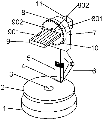
[0035] Such as figure 1As shown, the present invention provides a beauty lamp with multi-angle illumination, which includes a lamp base chassis 1, a rotatable turntable 2 is arranged above the lamp base chassis 1, and the lamp base chassis 1 and the rotatable A central connecting shaft 3 is connected between the turntables 2, and a rectangular installation groove 4 is provided on the upper surface of the rotatable turntable 2, and a lifting rod 5 is arranged i...


PUM


Abstract

The invention discloses a beautification lamp with a multi-angle irradiation function. The beautification lamp comprises a lamp holder base plate, wherein a rotatable turntable is arranged above the lamp holder base plate; a center connecting shaft is connected between the lamp holder base plate and the rotatable turntable; a rectangular installing groove is formed in the upper surface of the rotatable turntable; an ascending and descending rod is arranged in the installing groove; a bending connector is arranged at the side edge of the ascending and descending rod; the upper end of the ascending and descending rod is connected with a lamp disc installing seat; a lamp circular disc is arranged on the front surface of the lamp disc installing seat; the front surface of the lamp circular disc is provided with a front side installing plate; a round center hole is formed in the geometric center position of the lamp circular disc; a rotating lamp board is connected onto the front side installing plate; the rotating lamp board and the front side installing plate are connected through a connecting rotating shaft; a plurality of strip-shaped lamp bead fixing grooves are formed in the surface of the rotating lamp board; a plurality of lamp beads are arranged in the edge position of the front side installing plate; the back surface of the lamp board installing seat is connected with a lamp board driving motor. The beautification lamp solves the problem that a conventional beautification lamp has a small regulation angle and is only applicable to the use by a single person.

Description

technical field [0001] The invention relates to the technical field of beauty lamps, in particular to a beauty lamp with multi-angle irradiation. Background technique [0002] Introduction of LED beauty lamp LED high-tech photon skin rejuvenation beauty lamp adopts the principle of photodynamics to activate deep cells and allow the skin to perform better metabolism. After the light is absorbed by the skin, the light energy is converted into intracellular energy, which relaxes and strengthens microvessels and produces a photochemical reaction-enzymatic reaction with the skin, increasing the catalase (Catalase) that acts as a cell "guard" and "cleaner" and superoxide dismutase (SOD) activity. Increases the breakdown of adenosine triphosphate (ATP), a source of cellular energy generation. Increase glycogen and protein content, thereby promoting cell metabolism and synthesis. Stimulate the secretion of basic synthetic fiber growth factor (BFGF) and epidermal growth factor (EG...

Claims


Application Information

Patent Timeline
Patent Type & Authority Applications(China)
IPC IPC(8): F21S6/00F21V13/12F21V14/02F21V21/14F21V21/15F21V21/22F21V21/30A61N5/06
CPCF21S6/00F21V13/12F21V14/02F21V21/14F21V21/30F21V21/15F21V21/22F21V29/83A61N5/062F21Y2115/10A61N2005/0654A61N2005/0635A61N2005/0632
Inventor 马凯敏
Owner TOP TRI WUXI DESIGN CONSULTANTS
Why Eureka
Try Eureka