Pressure-stabilized simulated grouting test device and application method thereof

A technique of grouting test and grouting, which is applied in the field of grouting in geotechnical engineering, can solve the problems of repeated simulation of various working conditions and difficult control of grouting pressure, and achieve easy quantification of test results, grouting pressure and grouting pressure. Slurry volume can be controlled to achieve the effect of repeated use

Pending Publication Date: 2019-07-02
ZHENGZHOU UNIV
View PDF8 Cites 6 Cited by
  • Summary
  • Abstract
  • Description
  • Claims
  • Application Information

AI Technical Summary

Problems solved by technology

[0007] Aiming at the deficiencies in the above-mentioned background technology, the present invention proposes a stabilized pressure simulated grouting test device, which solves the technical problems that the existing grouting test cannot repeatedly simulate various working conditions, and the grouting pressure is difficult to control.

Method used


Image

  • Pressure-stabilized simulated grouting test device and application method thereof
  • Pressure-stabilized simulated grouting test device and application method thereof
  • Pressure-stabilized simulated grouting test device and application method thereof

Examples


Embodiment 1

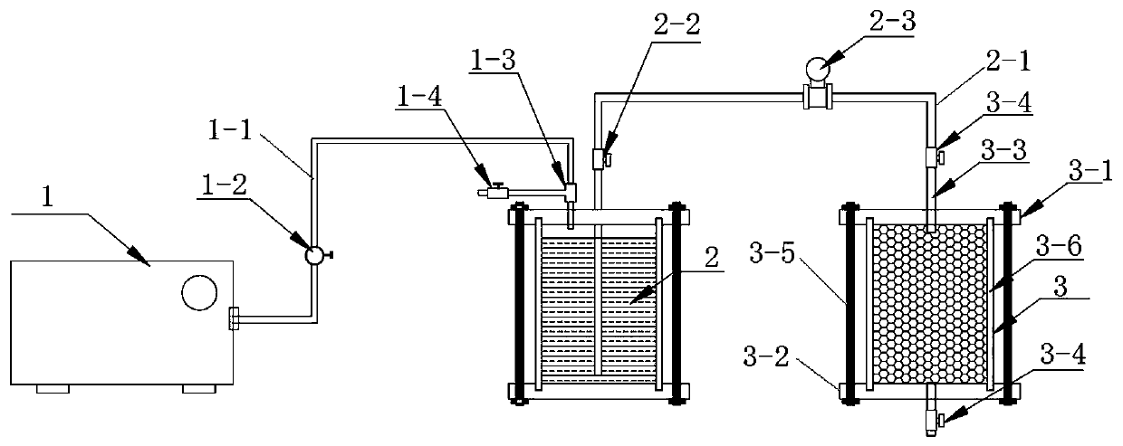
[0044] Embodiment 1, a kind of steady pressure simulated grouting test device, such as figure 1 and figure 2 As shown, the grout storage tank 2 is included, and the grout storage tank 2 is connected to the air compressor 1 through the first conduit 1-1, and the first conduit 1-1 is provided with a pressure regulating valve 1-2 ,, By adjusting the pressure regulating valve 1-2, the supply pressure value of the air compressor 1 to the grouting tank 2 can be adjusted. The slurry storage and injection tank 2 is connected to the sample mold through the second conduit 2-1, and the slurry in the slurry storage and injection tank 2 can be transported to the sample mold through the second conduit 2-1. By adjusting the pressure regulating valve 1- 2. The slurry under different pressure values ​​can be injected into the sample mold. The second conduit 2-1 is provided with a slurry outlet valve 2-2, and the opening and closing of the slurry outlet valve 2-2 controls the process of grou...

Embodiment 2

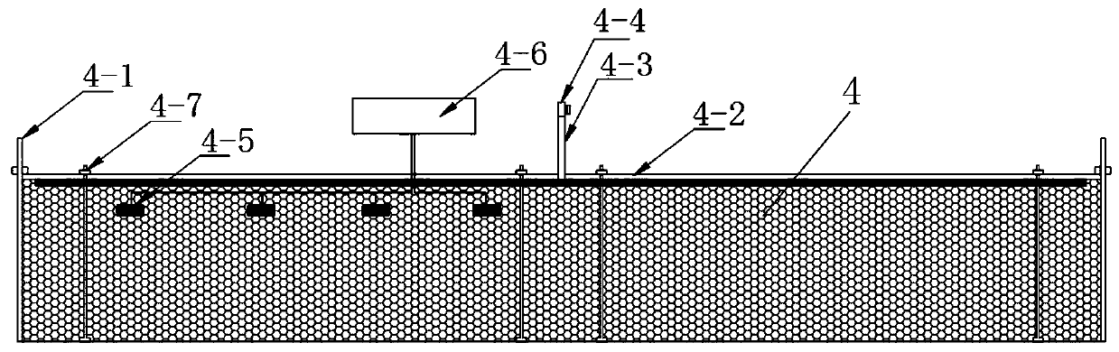
[0052] Embodiment 2, a kind of stable pressure simulated grouting test device, such as figure 2 As shown, the visualized slurry diffusion radius and real-time medium pressure detection sample mold 4 includes a metal cylinder 4-1 and a PMMA plate 4-2 sealed on the top of the metal cylinder 4-1, and the PMMA plate 4-2 passes through the second The screw assembly 4-7 is reinforced and connected to the top of the metal cylinder 4-1, the PMMA plate 4-2 is provided with a central hole, and a second inlet that is detachably connected to the second conduit 2-1 is inserted in the central hole. Serous duct 4-3. During the experiment, the visualization of the grouting radius of the structural layer can be realized through the PMMA plate 4-2, which is conducive to the quantification of data.

[0053] Further, a pressure sensor 4-5 is arranged inside the metal cylinder 4-1, and a signal collector 4-6 connected with the pressure sensor 4-5 is arranged outside the metal cylinder 4-1. The ...

Embodiment 3

[0055] Embodiment 3, a pressure-stabilizing simulated grouting test device, the first grout inlet valve 3-4 is set on the first grout inlet conduit 3-3, and the second grout inlet valve 3-3 is arranged on the second grout inlet conduit 4-3. The slurry inlet valve 4-4. The setting of the first slurry inlet valve 3-4 and the second slurry inlet valve 4-4 can further ensure the stability of the pressure control during the experiment.

[0056] Other structures of this embodiment are the same as those of Embodiment 2.


PUM


Abstract

The invention discloses a pressure-stabilized simulated grouting test device and an application method thereof. The technical problems that the existing grouting test cannot repeatedly simulate a plurality of working conditions and the grouting pressure is difficult to control are solved. The device provided by the invention comprises a slurry grouting tank which is connected with an air compressor through a first conduit. A pressure regulating valve is arranged on the first conduit. The slurry grouting tank is connected with a sample mold through a second conduit. The second conduit is provided with a slurry outlet valve. The sample mold is a visualized pressure infiltration sample mold or a visualized slurry diffusion radius and real-time medium pressure detection sample mold. The methodcan realize the grouting process of a grouted medium in a test room from compaction to split grouting, and can monitor the variation law of the top pressure and the diffusion radius between structural layers, and realizes the visualization of the grouting process and the controllability of the grouting pressure and the grout amount. The operation is simple, and the test results are easy to quantify.

Description

technical field [0001] The invention relates to the technical field of grouting in geotechnical engineering, in particular to a pressure-stabilizing simulated grouting test device and an application method thereof. Background technique [0002] With the development of my country's infrastructure, grouting technology is more and more widely used in active service, new construction, construction in progress, disaster prevention and control, repair and reinforcement. At present, while the grouting theory is being vigorously developed, the diffusion radius of the grout in the grouted medium, the law of pressure attenuation, the development of the grout veins, and the solidification of the grout to the grouted medium under different grouting pressures, etc. cannot be directly observed. [0003] The existing grouting technology has the following problems: [0004] In construction engineering, due to different working conditions, there is no uniform standard for the final pressur...

Claims


Application Information

Patent Timeline
Patent Type & Authority Applications(China)
IPC IPC(8): G01N33/24G01D21/02
CPCG01N33/24G01D21/02
Inventor 乐金朝庞冠洪孙杨张献平苏陈诚彭荣贵职子涵李文杰
Owner ZHENGZHOU UNIV
Why Eureka
Try Eureka