Biomass power generation device and method

A biomass power generation and generator technology, which is applied in the direction of hot gas variable displacement engine device, machine/engine, solid fuel combustion, etc., can solve the problems of unfavorable clean production and use, unfavorable pollution discharge, unfavorable and other problems, and achieve favorable cleanliness The effect of production and use, ensuring the quality of power generation, and improving production efficiency

Active Publication Date: 2019-07-05
大唐长春热力有限责任公司
View PDF7 Cites 4 Cited by
  • Summary
  • Abstract
  • Description
  • Claims
  • Application Information

AI Technical Summary

Problems solved by technology

[0010] The purpose of the present invention is to provide a biomass power generation device and method to solve the problem that the current biomass power generation device and method proposed in the above-mentioned background technology are not convenient for promoting raw materials, not conducive to speeding up the conveying process of raw materials, and not conducive to ensuring efficient operation Use is not conducive to ensuring the drying efficiency of raw materials, and makes the conveying work and drying work step by step, which greatly slows down the rate of combustion and power generation, which is not convenient to ensure the pressure of raw material extrusion molding, and is not conducive to ensuring raw material extrusion The stability after molding makes the raw materials easy to disperse, which is not conducive to ensuring the full combustion of raw materials, is not conducive to ensuring the full utilization of raw materials, is not conducive to ensuring the quality of power generation, is not convenient for the treatment of waste gas, waste water, and waste residue, and is not conducive to reducing pollution emissions. , which is not conducive to the use of clean production

Method used


Image

  • Biomass power generation device and method
  • Biomass power generation device and method
  • Biomass power generation device and method

Examples


Embodiment Construction

[0046] The following will clearly and completely describe the technical solutions in the embodiments of the present invention with reference to the accompanying drawings in the embodiments of the present invention. Obviously, the described embodiments are only some, not all, embodiments of the present invention. Based on the embodiments of the present invention, all other embodiments obtained by persons of ordinary skill in the art without making creative efforts belong to the protection scope of the present invention.

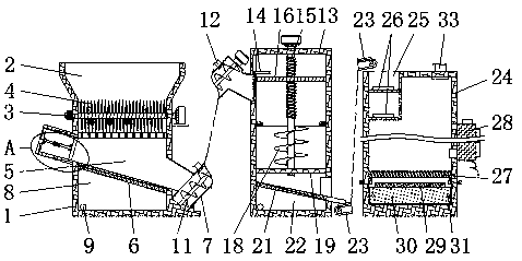
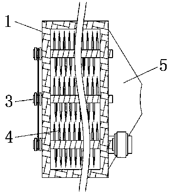
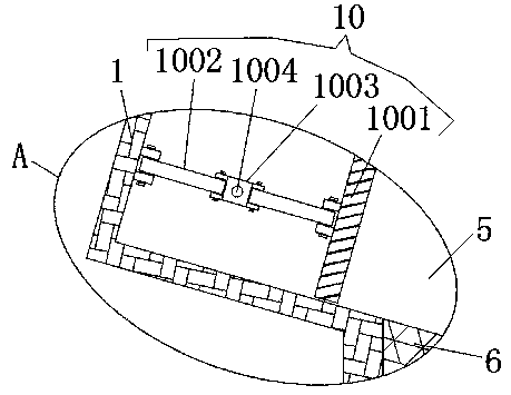
[0047] see Figure 1-12 , the present invention provides a technical solution: a biomass power generation device, including a pulverizer 1, a feed port 2, a pulverizing roller 3, a pulverizing blade 4, a feeding chamber 5, a first filter plate 6, a raw material pusher 7, First cavity 8, water outlet 9, material holding device 10, auger 11, air inlet 12, molding machine 13, cover plate 14, middle rod 15, pressing plate 16, top plate 17, extruding plate 18, form...


PUM


Abstract

The invention discloses a biomass power generation device and method. The device comprises a pulverizer and a stirling generator. A feeding opening is formed in the top end in the pulverizer, a pulverizing blade is arranged on the outer side of a pulverizing roller, the left side of a forming machine is connected with the top end of a raw material pushing machine, the upper portion of the left side of a combustor is arranged on the top end of a conveying belt, and the stirling generator is located on the outer side of the combustor. According to the biomass power generation device and method,raw material pushing is facilitated, conveying work and drying work are synchronously carried out, pressure of raw material extrusion forming can be conveniently ensured, stability after raw materialextrusion forming is ensured, the raw material is not prone to scattering, sufficient combustion of the raw material can be ensured, sufficient using of the raw material is ensured, power generation quality is ensured, production efficiency is improved, waste water, waste gas and waste slag can be treated, pollution emissijon can be reduced, and clean production is facilitated.

Description

technical field [0001] The invention relates to the technical field of biomass power generation, in particular to a biomass power generation device and method. Background technique [0002] As people's consumption of energy increases year by year, more and more people pay attention to the problem of energy consumption. Biomass power generation is a kind of renewable energy power generation that uses the biomass energy of biomass. Biomass power generation includes direct combustion of agricultural and forestry waste, gasification of agricultural and forestry waste, waste incineration power generation, landfill gas power generation, biogas power generation, etc. Combustion power generation is a power generation technology with a large power supply; [0003] Although the biomass power generation devices and methods used under the background of the prior art have gradually made great improvements, there are still certain deficiencies, such as: [0004] 1. It is not convenient t...

Claims


Application Information

Patent Timeline
Patent Type & Authority Applications(China)
IPC IPC(8): F02G1/043F02G1/053F23B40/00F23J1/06
CPCF02G1/043F02G1/053F23B40/00F23J1/06
Inventor 曹洋洋李青
Owner 大唐长春热力有限责任公司
Why Eureka
Try Eureka