Small-size high-efficiency electric heating device with waste heat recovery function

An electric heating device and waste heat recovery technology, applied in fluid heaters, water heaters, lighting and heating equipment, etc., can solve the problems of small volume and high power density components that are easy to burn out, and achieve excellent electric heating performance and low shell temperature , the effect of saving energy

Pending Publication Date: 2019-07-05
WUHU ALDOC TECH CO LTD
View PDF0 Cites 2 Cited by
  • Summary
  • Abstract
  • Description
  • Claims
  • Application Information

AI Technical Summary

Problems solved by technology

[0003] The purpose of the present invention is to solve the shortcoming that the small volume high power density components in the prior art are easy to burn out, and propose a small volume high efficiency electric heating device with waste heat recovery function

Method used


Image

  • Small-size high-efficiency electric heating device with waste heat recovery function
  • Small-size high-efficiency electric heating device with waste heat recovery function
  • Small-size high-efficiency electric heating device with waste heat recovery function

Examples


Embodiment 1

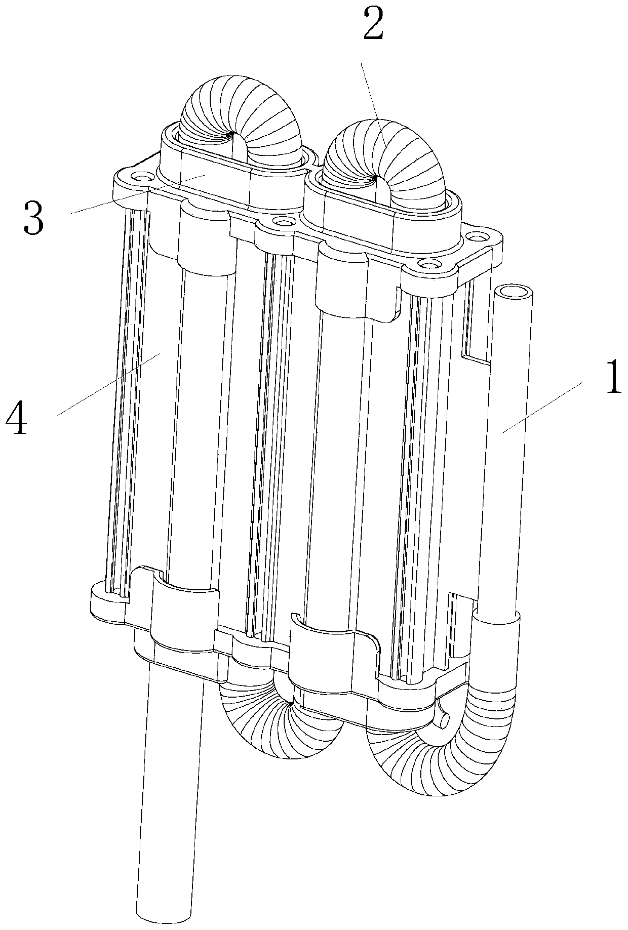
[0024] refer to Figure 1-3 , a small-volume high-efficiency electric heating device with a waste heat recovery function, including a plurality of electric heating tubes 5, the electric heating tube 5 is a nano-film electric heating tube based on a heat-conducting tube, and the nano-electric heating film has a high thermal efficiency High environmental protection heating film, the heat conduction tube is one of inorganic tubes, quartz tubes, ceramic tubes, high borosilicate glass tubes, and metal tubes with insulating coatings. Multiple electric heating tubes 5 are connected through the connecting tube 2 to form a liquid Electric heating passage, a plurality of electric heating tubes 5 are provided with a heat conduction shell 4, the heat conduction shell 4 is made of a material with good thermal conductivity, preferably the heat conduction shell 4 is aluminum, stainless steel, carbon steel, copper, alloy, and the electric heating tube 5 The upper and lower ends are fixed toge...

Embodiment 2

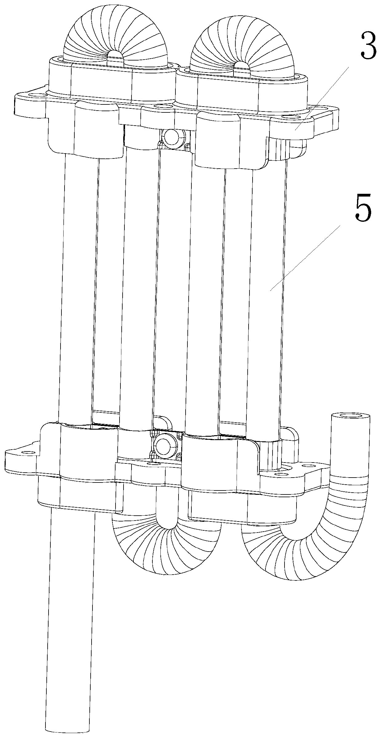
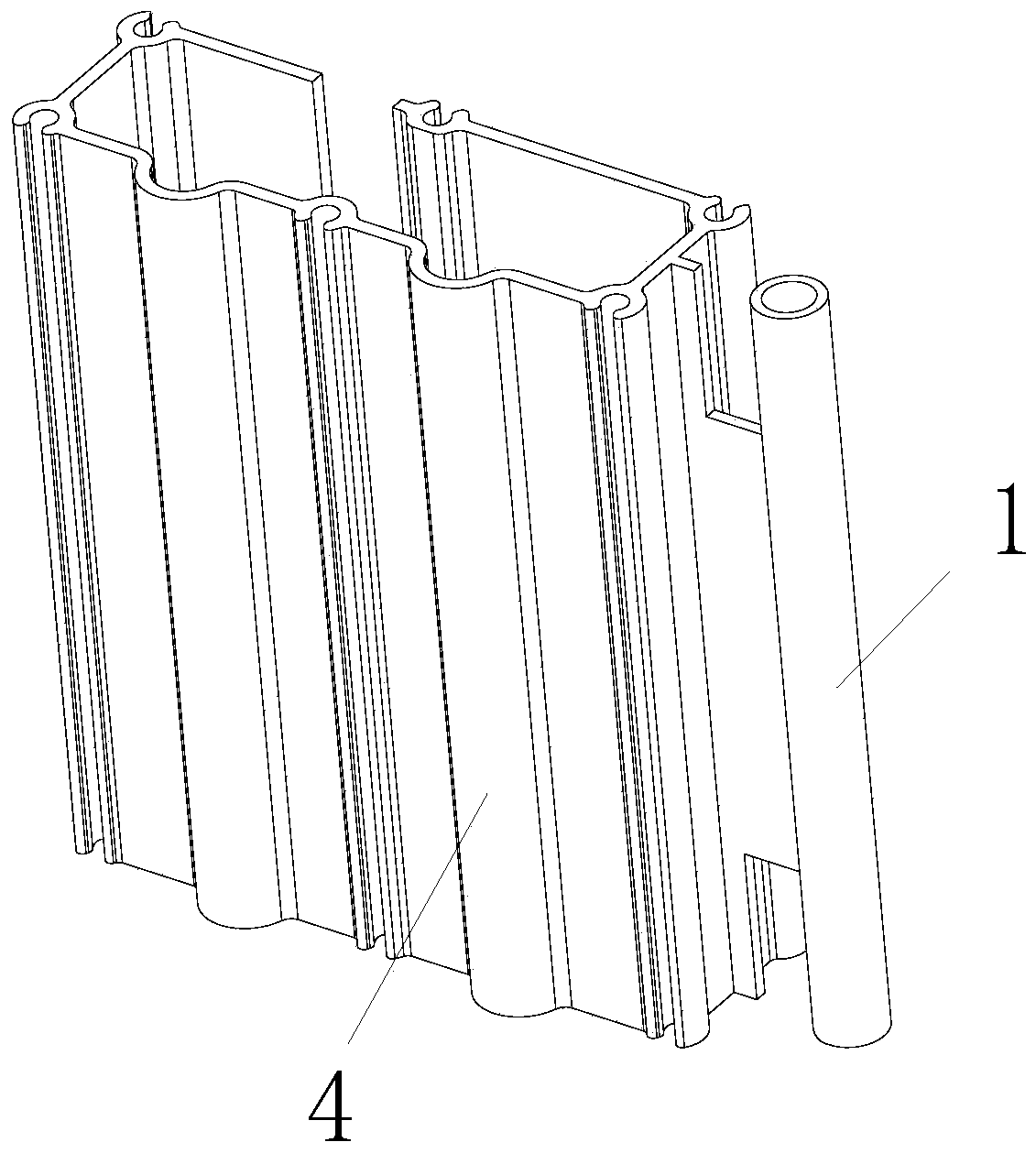
[0028] refer to Figure 4-5 , a small-volume high-efficiency electric heating device with a waste heat recovery function, including a plurality of electric heating tubes 5, the electric heating tube 5 is a nano-film electric heating tube based on a heat-conducting tube, and the heat-conducting tube is an inorganic tube, quartz One of tubes, ceramic tubes, high borosilicate glass tubes, and metal tubes with insulating coatings. Multiple electric heating tubes 5 are connected through the connecting tube 2 to form a liquid electric heating path. Multiple electric heating tubes 5 are sleeved outside There is a heat conduction shell 4, and the upper and lower ends of the electric heating tube 5 are fixed together with the heat conduction shell 4 through the fixing piece 3. The heat conduction shell 4 is integrally formed with a water inlet pipe 1, and the water inlet pipe 1 communicates with the water inlet end of the liquid electric heating channel. The water inlet pipe 1 is place...


PUM


Abstract

The invention relates to the technical field of liquid electric heating, in particular to a small-size high-efficiency electric heating device with a waste heat recovery function. The device comprisesa plurality of electric heating tubes, the plurality of electric heating tubes communicates with each other through connecting tubes to form a liquid electric heating channel, a heat conduction shellare arranged outside the electric heating tubes in a sleeved mode, the upper ends and the lower ends of the electric heating tubes are fixed together with the heat conduction shell through fixing pieces, the heat conduction shell is integrally formed with a water inlet tube, and the water inlet tube communicates with the water inlet end of the liquid electric heating channel. According to the device, a liquid electric heating assembly can effectively reduce the size of the assembly under the same power, the occupied volume of the space is reduced, meanwhile, heat can be recycled, so that theheat efficiency is improved, the energy is saved, the environment is protected, and meanwhile, the temperature of the outer sleeve shell is kept low and the outer sleeve shell is convenient to use ina narrow space.

Description

technical field [0001] The invention relates to the technical field of liquid electric heating, in particular to a small-volume high-efficiency electric heating device with a waste heat recovery function. Background technique [0002] With the continuous advancement of science and technology, the electrical equipment involved in home life gradually tends to be miniaturized. The miniaturization of electrical equipment can reduce the space occupied by the volume. In order to make electrical equipment smaller and meet people's normal needs, electrical manufacturers will choose If the heating element with high efficiency and high power density dissipates slowly or the heat of the liquid is not absorbed in time, it will cause the heating element to burn out. At the same time, if the structural design is unreasonable, it will cause energy waste. At the same time, most of the current instant heating components are placed vertically, which limits the overall design and application s...

Claims


Application Information

Patent Timeline
Patent Type & Authority Applications(China)
IPC IPC(8): F24H1/10F24H9/00F24H9/18F24H9/20
CPCF24H1/102F24H9/0005F24H9/1818F24H9/2028
Inventor 胡如国吴茂国赵丽丽
Owner WUHU ALDOC TECH CO LTD
Why Eureka
Try Eureka