Measuring Method of Aperture Size of Parts Based on Machine Vision Technology

A technology of machine vision and measurement methods, applied in measurement devices, instruments, image analysis, etc., can solve the problems of cumbersome process, difficult calibration of parts hole surface, low accuracy, etc., to simplify the measurement process, improve measurement accuracy, and correct image distortion. Effect

Active Publication Date: 2020-11-03
JILIN UNIV
View PDF8 Cites 1 Cited by
  • Summary
  • Abstract
  • Description
  • Claims
  • Application Information

AI Technical Summary

Problems solved by technology

[0005] The purpose of the present invention is to provide a method for measuring the aperture size of parts based on machine vision technology, which solves the problem that the surface of the existing part hole is not easy to calibrate and the accuracy is not high, and the chamfering structure existing on the edge of the part hole makes the edge blurred in the imaging photo. As a result, the photo of the aperture of the part cannot be accurately extracted directly through the edge detection technology in machine vision, resulting in the technical problems of cumbersome process, low efficiency and poor accuracy in the existing application of machine vision technology to measure the aperture size of the part
The invention calibrates the external parameters of the hole surface by measuring the coordinates of the center points of the end faces of three small tubes, which solves the problem that the external parameters of the hole surface are not easy to calibrate and the accuracy is not high, and then uses the geometric relationship between the small tubes in the hole to solve the problem of the hole surface The diameter size eliminates the influence of the edge chamfer of the measured hole on the edge image point of the detection hole, improves the measurement accuracy, and realizes non-contact measurement of the hole size

Method used


Image

  • Measuring Method of Aperture Size of Parts Based on Machine Vision Technology
  • Measuring Method of Aperture Size of Parts Based on Machine Vision Technology
  • Measuring Method of Aperture Size of Parts Based on Machine Vision Technology

Examples


Embodiment Construction

[0038] The detailed content and specific embodiments of the present invention will be further described below in conjunction with the accompanying drawings.

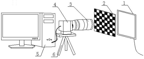
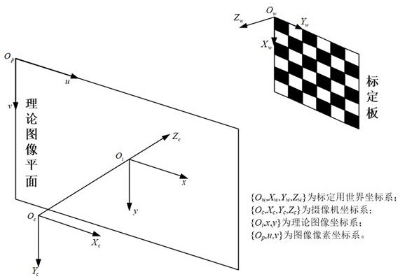
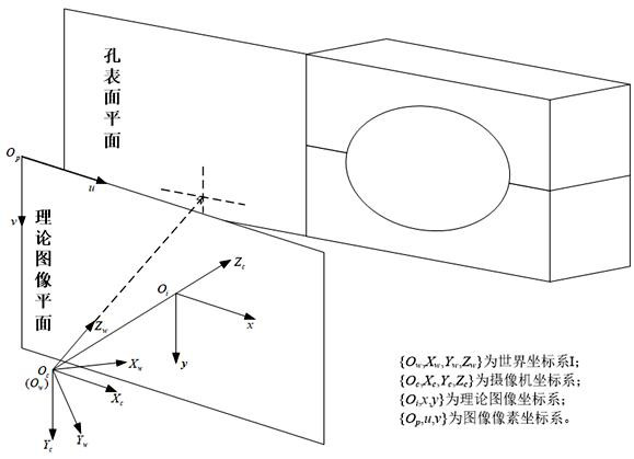
[0039] See Figure 1 to Figure 6 As shown, the method for measuring part aperture size based on machine vision technology of the present invention uses the conditions for setting the formation of the world coordinate system I to establish the transformation relationship equation between the world coordinate system I and the camera coordinate system, thereby establishing the aperture measurement model; this method It is first proposed to place three small circular tubes of the same size in the part hole and collect the image of the part hole end surface, and obtain the curve equation of the inner and outer edge of the small circular tube end surface by curve fitting on the theoretical image plane. Establish new world coordinate systems II and III based on the adjacent small circular tubes, obtain the world coordinates of the ...


PUM


Abstract

The invention relates to a part aperture size measurement method based on a machine vision technology and belongs to the machine vision measurement technology field. Non-contact measurement of a partaperture size can be realized. After an internal parameter and a distortion coefficient of a CCD camera are calibrated, three same small circular tubes with a known size are inserted into a part holeand an image is shot, and inner and outer edge curves of the end surfaces of the small circular tubes are fit; then, a world coordinate system is reconstructed through using the adjacent small circular tubes, a world coordinate of a center point of the end surfaces of the small circular tubes is calculated, and a transformation relationship between the world coordinate system and a camera coordinate system is solved based on that; and finally, since an edge chamfer of the part hole affects an edge image point for detecting the part hole, a method of fitting part hole edge curves is not used, but a geometrical relationship between the part hole and the small circular tubes is used to calculate the part aperture size. Through using a machine vision measurement technology, the method of placing the three small circular tubes with the same size in the part hole is adopted to realize the non-contact measurement of the part aperture size.

Description

Technical field [0001] The present invention relates to the technical field of machine vision measurement, in particular to a method for measuring the aperture size of a part based on machine vision technology. Background technique [0002] In the heavy industry, agricultural machinery, automobile and other machinery industries, many parts have holes. For example, automobile gearboxes, machine tool spindle boxes, bearing seats, etc. generally have holes of different sizes. Parts with holes will inevitably undergo different degrees of deformation during processing, manufacturing, surface heat treatment, etc., resulting in large errors in the aperture size. If these deformations or excessive errors cannot be effectively and accurately measured, the subsequent Various problems will be brought about in the finishing or assembly process, which will directly affect the quality of the product, and even directly affect the rejection rate of the product. Therefore, in order to reduce the...

Claims


Application Information

Patent Timeline
Patent Type & Authority Patents(China)
IPC IPC(8): G01B11/12G06T7/70
CPCG01B11/12G06T7/70
Inventor 谭庆昌苗建伟邵天池原敏乔刘思远包昊菁
Owner JILIN UNIV
Why Eureka
Try Eureka