
Real-time non-uniformity correction system and method for large-scale infrared focal plane

A non-uniformity correction and infrared focal plane technology, applied in the field of infrared imaging, can solve the problems of difficult implementation and high DSP operating frequency, and achieve the effect of reducing operating frequency, reducing volume, and improving system integration

Inactive Publication Date: 2019-07-05
上海德运光电技术有限公司
View PDF5 Cites 3 Cited by
  • Summary
  • Abstract
  • Description
  • Claims
  • Application Information

AI Technical Summary

Problems solved by technology

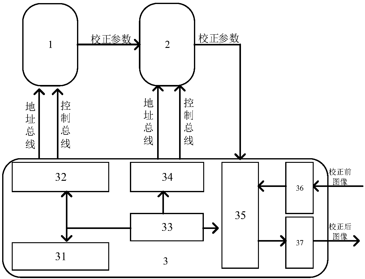
However, since the DSP has only one set of address and data buses, and the non-uniform correction involves the reading of two sets of correction coefficients and image data, the DSP is required to multiplex its address bus, which is connected to the memory storing the correction coefficients and original image data, and then time-sharing Correction coefficients and image data alone require a higher operating frequency of the DSP to reach up to Ghz, which is difficult to achieve in practical applications

Method used


Image

  • Real-time non-uniformity correction system and method for large-scale infrared focal plane
  • Real-time non-uniformity correction system and method for large-scale infrared focal plane
  • Real-time non-uniformity correction system and method for large-scale infrared focal plane

Examples


Embodiment

[0030] Large-scale infrared focal planes have a large number of detector pixels and high real-time requirements. No matter which correction algorithm is selected, gain correction parameters and offset correction parameters are required. And each detector pixel requires a set of correction parameters, therefore, as the number of detector pixels increases, the required correction parameters also increase. Moreover, in order to obtain a better correction effect, a more advanced and precise correction algorithm must be used, such as a multi-point correction algorithm. The higher the accuracy requirement, the more segments the multi-point segmented correction algorithm has. The sensor pixel needs a set of correction coefficients, so as the correction accuracy requirements increase, the correction parameters will increase. It can be seen from this that how to solve the high-speed access of a large number of correction coefficients is one of the problems that must be considered to co...


PUM


Abstract

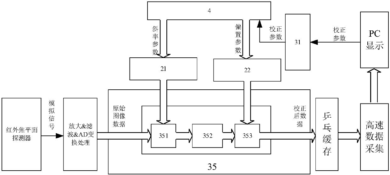
The invention relates to a real-time non-uniformity correction system and method for a large-scale infrared focal plane. The correction system comprises a large-capacity non-volatile memory, a parameter memory SRAM and a logic time sequence control circuit; the logic time sequence control circuit comprises a main control module as well as a non-volatile memory read / write control module, an SRAM read / write control module, a parameter up-pouring module and a correction operation module which are connected with the main control module; the correction system further comprises an image data input interface and an image data output interface which are connected with the correction operation module; the large-capacity non-volatile memory is connected with the parameter memory SRAM and the non-volatile memory read / write control module; and the parameter memory SRAM is also connected with the SRAM read / write control module and the correction operation module. Compared with the prior art, the system and method of the invention can effectively ensure correction speed while ensuring operation precision and have the advantages of large parameter storage capacity, high operation real-time performance and the like, and can be applied to the real-time correction of large-scale area array detectors.

Description

technical field [0001] The invention relates to the technical field of infrared imaging, in particular to a large-scale infrared focal plane real-time non-uniformity correction system and method thereof. Background technique [0002] Infrared detectors are the core of infrared detection systems. With the development of current detection technology, infrared imaging detection systems, especially infrared hyperspectral imaging detection systems, increasingly need to use large-scale infrared focal plane detectors. However, due to many Due to control factors and technological level limitations, the responsivity and DC bias of each photosensitive element of the infrared focal plane detector cannot be completely consistent. This non-uniformity of response and bias will make the imaging system Inconsistencies in the output at different degrees, manifested as spots or stripes with uneven brightness and darkness on the image, that is, nonuniformity of the image (Nonuniformity), also ...

Claims


Application Information

Patent Timeline
Patent Type & Authority Applications(China)
IPC IPC(8): G01J5/00
CPCG01J5/00G01J5/80
Inventor 郁雷
Owner 上海德运光电技术有限公司
Learn More