
Heat recovery coke oven high temperature and ultra-high pressure reheat waste heat boiler

A technology of waste heat boiler and ultra-high pressure, which is applied in the field of heat recovery coke oven high-temperature and ultra-high pressure reheat waste heat boiler, which can solve the problems of low exhaust gas pressure, easy corrosion, and low temperature of inlet and exhaust gas, and achieve high stability, temperature and air pressure Increased effect

Active Publication Date: 2019-07-09
HANGZHOU HANGGUO INDUSTRIAL BOILER CO LTD
View PDF6 Cites 1 Cited by
  • Summary
  • Abstract
  • Description
  • Claims
  • Application Information

AI Technical Summary

Problems solved by technology

[0006] The purpose of the present invention is to provide a heat recovery coke oven high temperature and ultra-high pressure reheating waste heat boiler, which solves the problem that the existing heat recovery coke oven reheating waste heat boiler can handle the low temperature of the incoming steam and the low pressure of the tail gas, which leads to power generation efficiency lower defect
[0007] Another object of the present invention is to provide a heat recovery coke oven high temperature and ultra-high pressure reheat waste heat boiler, which solves the problem that the heating surface of the waste heat boiler body of the existing heat recovery coke oven reheat waste heat boiler is easily corroded

Method used


Image

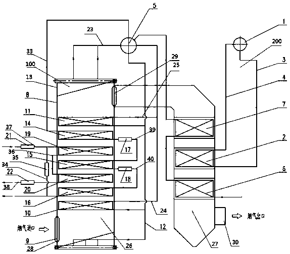
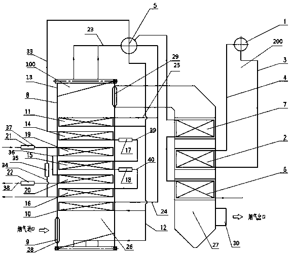
  • Heat recovery coke oven high temperature and ultra-high pressure reheat waste heat boiler
  • Heat recovery coke oven high temperature and ultra-high pressure reheat waste heat boiler

Examples


Embodiment Construction

[0031] The specific implementation manners of the present invention will be further described in detail below in conjunction with the accompanying drawings and embodiments. The following examples are used to illustrate the present invention, but are not intended to limit the scope of the present invention.

[0032] In the description of the present invention, unless otherwise stated, the meaning of "plurality" is two or more; the terms "upper", "lower", "left", "right", "inner", "outer" , "front end", "rear end", "head", "tail", etc. indicate the orientation or positional relationship based on the orientation or positional relationship shown in the drawings, and are only for the convenience of describing the present invention and simplifying the description, rather than Nothing indicating or implying that a referenced device or element must have a particular orientation, be constructed, and operate in a particular orientation should therefore not be construed as limiting the i...


PUM


Abstract

The invention provides a heat recovery coke oven high temperature and ultra-high pressure reheat waste heat boiler. The heat recovery coke oven high temperature and ultra-high pressure reheat waste heat boiler comprises a low pressure evaporation system, an ultra-high pressure section evaporation system and a reheat system. The ultra-high pressure section evaporation system comprises a boiler body, a protective evaporator is installed on one side of the interior of the boiler body, and an ultra-high pressure section evaporator is installed on the other side of the boiler body; the boiler bodylocated at the back end of the ultra-high pressure section evaporator is externally connected with an ultra-high pressure section boiler tube through a first extraction pipe; the ultra-high pressure section boiler tube is further externally connected with the protective evaporator through a falling pipe, and a protective evaporation pipe communicates with the ultra-high pressure section boiler tube through a second extraction pipe; and the ultra-high pressure section boiler tube is further externally connected with the ultra-high pressure section evaporator through the falling pipe, and the ultra-high pressure section evaporator communicates with the ultra-high pressure section boiler tube through a third extraction pipe. The defects that the power generation efficiency is low due to the fact that steam inlet exhaust gas temperature dealt by an existing heat recovery coke oven reheat waste heat boiler is low, and the tail gas pressure is low are overcome.

Description

technical field [0001] The invention relates to the field of high-temperature and ultra-high pressure waste heat boilers, in particular to a heat recovery coke oven high temperature and ultra-high pressure reheating waste heat boiler. Background technique [0002] Heat recovery coke oven refers to a kind of coke produced by coking coal during the coking process, its chemical products, coke oven gas and some harmful substances are reasonably and fully burned inside the coke oven, and the heat of high-temperature waste gas is recovered for power generation or other purposes coke oven. Due to its unique furnace structure and process technology, the heat recovery coke oven operates under negative pressure in the carbonization chamber during the coking process, does not leak smoke and dust, does not recover chemical products and purify coke oven gas, and rarely produces pollutants, so heat recovery The coke oven solves the generation of major pollutants in the coking process, an...

Claims


Application Information

Patent Timeline
IPC IPC(8): F22B1/18F27D17/00
CPCF22B1/1892F27D17/004F27D2017/006F27M2001/045Y02P10/25
Inventor 陈庆实刘杨瞿云富王峻张同伟周旭东张峰
Owner HANGZHOU HANGGUO INDUSTRIAL BOILER CO LTD
Learn More